
Technical Product Specification

Intel® RAID Controller SRCSAS18E Hardware
Revision 1.01
Intel order number D61769-001
7
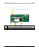
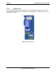
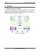
2.3.5.2 LED Placement and Function
Two functional LED sets are incorporated into the Intel
®
RAID controller SRCSAS18E, and one
set is incorporated into the optional battery.
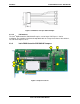
Figure 3. Intel
®
RAID Controller SRCSAS18E LED Locations
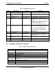
Callout Description
1 Functional code LEDs are for factory use. No decode of these LEDs will be provided.
2 Dirty Cache: LED connector at J10 and LED on the Intel
®
Portable Cache Module 2 (battery) signifies that
data in memory has not been written to disk. Data will be held in memory until it is written to disk.
3 Host bus LED signals that the controller is operational.