
Technical Product Specification


Intel
®
Server Chassis H2000 Family TPS Power Sub-System
Revision 1.0 11
Intel order number: G59059-001
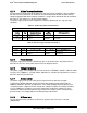
PSU Output Connector
A18
+12V
B18
+12V
A19
PMBus SDA*
B19
A0* (SMBus address)
A20
PMBus SCL*
B20
A1* (SMBus address)
A21
PSON
B21
12V STBY
A22
SMBAlert#
B22
Cold Redundancy Bus*
A23
Return Sense
B23
12V load share bus
A24
+12V Remote Sense
B24
No Connect
A25
PWOK
B25
CRPS Compatibility Check pin*
*: Refer to the spec of CRPS Common Requirements specification.
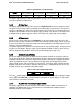
3.1.6 Handle Retention
The power supply has a handle to assist extraction. The module is able to be inserted and
extracted without the assistance of tools. The power supply also has a latch which retains the
power supply into the system and prevents the power supply from being inserted or extracted
from the system when the AC power cord is pulled into the power supply.
The handle protects the operator from any burn hazard through the use of industrial designed
plastic handle or equivalent material.
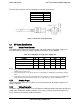
3.1.7 LED Marking and Identification
The power supply is using a bi-color LED: Amber and Green for status indication. Below are
table showing the LED states for each power supply operating state.
Table 9. Power Supply Status LED
Power Supply Condition
LED State
Output ON and OK
Solid GREEN
No AC power to all power supplies
OFF
AC present/Only 12VSB on (PS off) or PS in Cold
redundant state
1Hz Blink GREEN
AC cord unplugged or AC power lost; with a second
power supply in parallel still with AC input power.
Solid AMBER
Power supply warning events where the power supply
continues to operate; high temp, high power, high current,
slow fan.
1Hz Blink Amber
Power supply critical event causing a shutdown; failure,
OCP, OVP, Fan Fail
Solid AMBER
Power supply FW updating
2Hz Blink GREEN
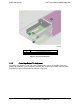
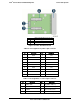
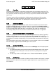
3.1.8 Power Cage with Power Distribution Board
The power cage is at the middle of the chassis, consists of two Power Distribution Boards (PDB)
to support Common Redundant Power Supplies (CRPS).
Below is the power system overview.