
Service Guide for Intel Server System H2000WP

Hardware Installations and Updates
Intel
®
Server System H2000WP Family Service Guide 23
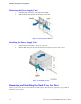
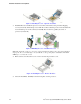
Figure 35. Installing Processor – Close the Load Plate
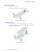
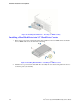
6. Latch the Locking Lever. Push down on the locking lever on the CLOSE 1st side (see letter A).
Slide the tip of the lever under the notch in the load plate (see letter B). Make sure the load
plate tab engages under the socket lever when fully closed. Repeat the steps to latch the locking
lever on the other side (see letter C). Latch the levers in the order as shown.
Figure 36. Installing Processor – Latch the Locking Lever
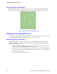
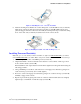
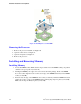
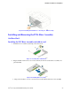
Installing Processor Heatsink(s)
Note: The processor heatsink for CPU1 and CPU2 are different. FXXCA84X106HS is for CPU1,
while FXXEA84X106HS is for CPU2. Mislocating the heatsink will cause serious thermal damage!
1. Remove the protective film on the TIM if present (see letter A).
2. Align heatsink fins to the front and back of the chassis for correct airflow. Airflow goes from
front-to-back of chassis (see letter B).
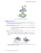
Each heatsink has four captive fasteners and should be tightened in a diagonal manner using the
following procedure:
3. Using a #2 Phillips* screwdriver, start with screw 1 and engage screw threads by giving it two
rotations and stop (see letter C). (Do not fully tighten.)
4. Proceed to screw 2 and engage screw threads by giving it two rotations and stop (see letter D).
Similarly, engage screws 3 and 4.
5. Repeat steps C and D by giving each screw two rotations each time until each screw is lightly
tightened up to a maximum of 8 inch-lbs torque (see letter E).