
Quick Install Guide

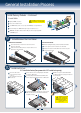
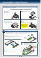
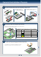
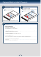

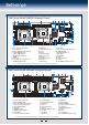
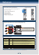
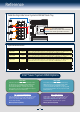
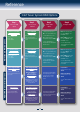
Table Of Contents
9
General Installation Process
14
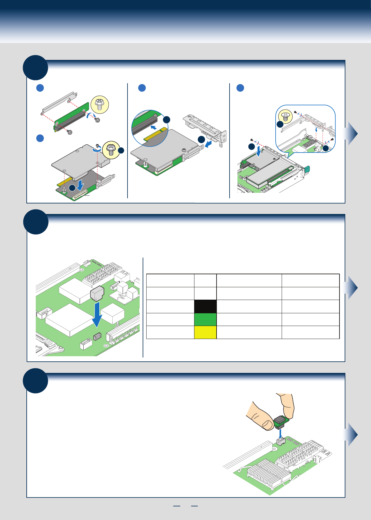
Install
Intel® Remote Management Module 4 (
optional)
Locate the RMM4 Lite connector, carefully pickup the Intel
®
RMM4 Lite module, match the
alignment pin of the module and the connector on server board, then press to install.
RMM4 Lite
Connector
13
Install Intel® RAID C600 Upgrade Key (optional)
Intel® RAID C600 Storage Upgrade Key Options for S2600JF and S2600WP
Locate the white 4-pin key header next to RISER SLOT_1. Carefully pickup the Intel
®
RAID C600 Upgrade Key.
Match the Key and connector orientation and press down to install.
Note: The 8-port Storage Upgrade Key can also implement the RAID function for S2600JF, but only 4 ports (SCU0)
can be configured as proper RAID level.
Intel® RAID C600
Upgrade Key Options
(Intel Product Codes)
Key Color Intel® RAID C600 Upgrade Key
Description
S2600JF SCU RAID availability
Description
Default – No option key
installed
N/A 4 Port SATA with Intel
®
ESRT RAID
0,1,10 and Intel
®
RSTe RAID 0,1,5,10
4 Port SATA with Intel
®
ESRT
RAID
0,1,10 and Intel
®
RSTe
RAID 0,1,5,10
RKSATA4R5
Black
4 Port SATA with Intel
®
ESRT2 RAID
0,1, 5, 10 and Intel
®
RSTe RAID
0,1,5,10
4 Port SATA with Intel
®
ESRT2
RAID
0,1, 5, 10 and Intel
®
RSTe
RAID 0,1,5,10
RKSATA8
Blue
8 Port SATA with Intel
®
ESRT2 RAID
4 Port SATA with Intel
®
ESRT2
0,1,5,10
RAID 0,1,5,10
RKSAS4
Green
4 Port SAS with Intel
®
ESRT2 RAID
0,1, 10 and Intel
®
RSTe RAID 0,1,10
4 Port SAS with Intel
®
ESRT2
RAID 0,1, 10 and Intel
®
RSTe
RAID 0,1,10
RKSAS4R5
Yellow
4 Port SAS with Intel
®
ESRT2 RAID
0,1, 5, 10 and Intel
®
RSTe RAID
0,1,10
4 Port SAS with Intel
®
ESRT2
RAID 0,1, 5, 10 and Intel
®
RSTe
RAID 0,1,10
®
®
OPEN 1st
CLOSE 1st
STOR_UPG_KEY
12
Install I/O Module Riser and Carrier Assembly on Riser Slot 2
1
Install Riser to riser bracket.
2
Install I/O Module to I/OM Carrier and
fasten with screw.
(See letter “B”)
3
Attach IOM bracket to IOM carrier
(see letter “D”), and then plug-in the IOM
assembly into the riser slot. (See letter “C”)
4
Install I/OM assembly and add-in card assembly (if any)
using screws. (See letters “F”, “E”, and “G”)
B
I/O Connector
I/O Module
A
OPEN 1st
CLOSE 1st
I/O Module
F
Add-in Card
G
E
I/O Module
D
C