
Quick Install Guide

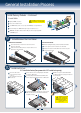
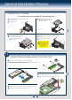
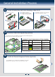
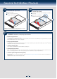

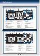
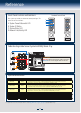
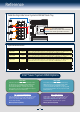
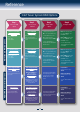
Table Of Contents
6
General Installation Process
8
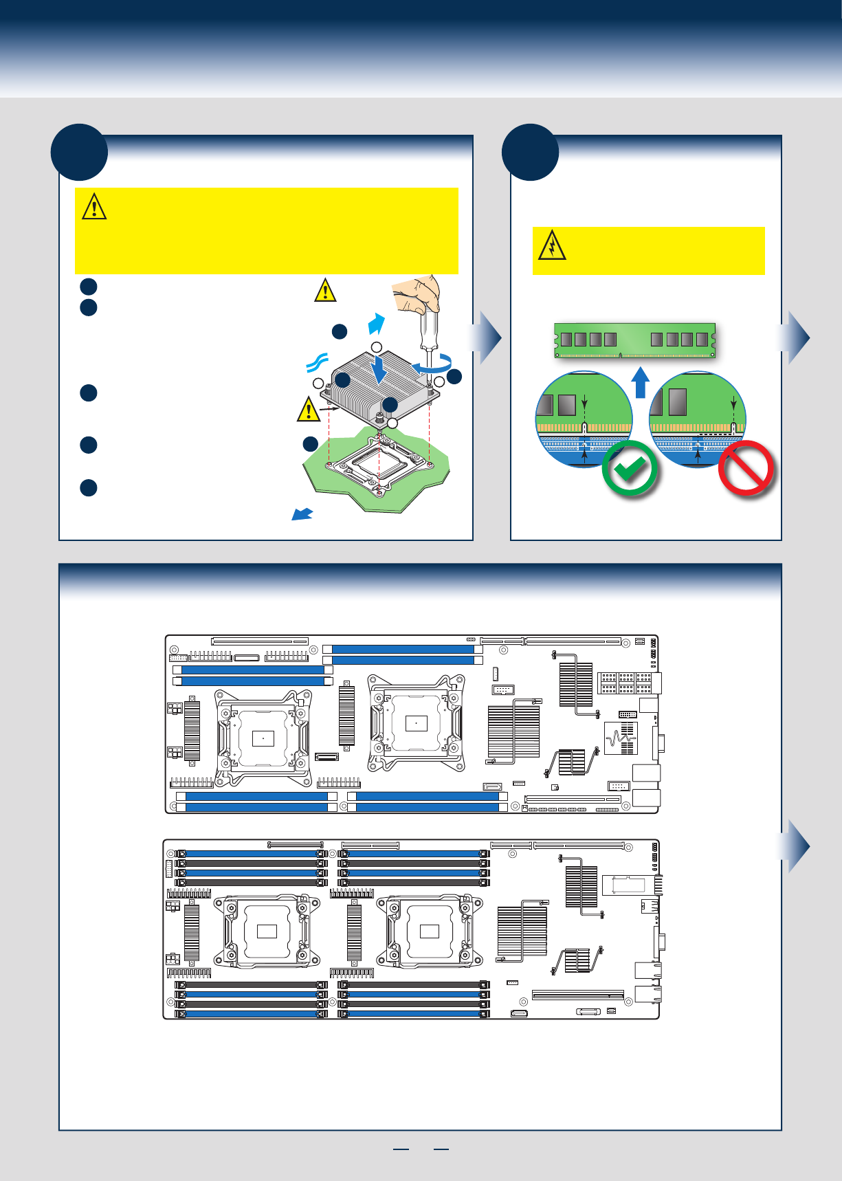
Install Memory Modules
DDR3 DIMM Memory Identification:
Other
Memory
DDR3
CAUTION: Observe normal ESD (ElectroStatic
Discharge) procedures to avoid possible damage to
system components.
DIMM notch and socket bump must align as shown below.
7
Install Processor Heatsink(s)
Note: Heatsink styles may vary.
Remove the protective film on the TIM if present.
D
CAUTION: The heatsink has thermal interface material (TIM) on the underside of it.
Use caution so that you do not damage the thermal interface material.
Use gloves to avoid sharp edges.
CPU socket 1 heat sink is different from CPU socket 2 heat sink. In the Server System
H2000JF family, FXXCA90X90HS is for CPU socket 1 and FXXEA90X90HS is for
CPU socket 2. In the Server System H2000WP family, FXXCA84X106HS isfor CPU1, while
FXXEA84X106HS is for CPU2." Mis-locating the heatsink will cause serious thermal damage!
E
C
A
B
Align heatsink fins to the front and back of
the chassis for correct airflow.
Airflow goes from front-to-back of chassis.
Each heatsink has four captive fasteners and
should be tightened in a diagonal manner using
the following procedure:
Using a #2 Phillips* screwdriver,
start with screw 1 and engage screw
threads by giving it two rotations
and stop. (Do not fully tighten.)
Proceed to screw 2 and engage screw
threads by giving it two rotations and stop.
Similarly, engage screws 3 and 4.
Repeat steps C and D by giving each
screw two rotations each time until each
screw is lightly tightened up to a
maximum of 8 inch-lbs torque.
CAUTION:
Do not
over-tighten
fasteners.
C
OPEN 1st
CLOSE 1st
Processor
Socket
AIRFLOW
Chassis Front
2
3
1
4
A
B
TIM
D
E
Install Memory Modules ... Continued
Memory Configurations and Population Order:
Intel® Server Board S2600JF
Intel® Server Board S2600WP
For best performance, a minimum of four DIMMs per CPU is recommended, populated in the blue slot of each memory channel.
In a single-processor configuration, always populate A1 DIMM first.
In a dual-processor configuration, always populate A1 DIMM first for CPU 1 and E1 DIMM first for CPU2.
Note: For additional memory configurations, see the Service Guide on the Intel
®
Server Deployment Toolkit CD that accompanied your Intel
®
Server Board
S2600WP
, or go to http://www.intel.com/support/motherboards/server/. (post-production)
Memory sizing and configuration is supported only for qualified DIMMs approved by Intel. For a list of supported memory, see the tested memory list at
http://www.intel.com/support/motherboards/server/. (post-production)
DIMM G1
DIMM G2
DIMM H1
DIMM H2
DIMM F2
DIMM F1
DIMM E2
DIMM E1
DIMM B2
DIMM B1
DIMM A2
DIMM A1
DIMM C1
DIMM C2
DIMM D1
DIMM D2
DIMM A1
DIMM B1
DIMM D1
DIMM C1
DIMM H1
DIMM G1
DIMM E1
DIMM F1