Intel® Server System H2000JF & H2000WP Quick Installation User's Guide Thank you for buying an Intel® Server System. The following information will help you assemble your Intel® Server System and install components. If you are not familiar with ESD [Electrostatic Discharge] procedures used during system integration, see the complete ESD procedures described in your Service Guide. This guide and other supporting documents are located on the web at: http://www.intel.com/support. * 12 x 3.
( This page is intentionally left blank.
Table of Contents System Overview (Intel® Server System H2000JF Family)..........................................1 System Overview (Intel® Server System H2000WP Family) ......................................2 General Installation Process ..........................................................................................................3 Preparing the System ...................................................................................................... 3 Install/Remove the Power Supply Unit ...
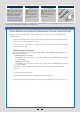
Warning Warning Caution Tools Required Read all caution and safety statements in this document before performing any of the instructions. Also see the Intel ® Server Board and Server Chassis Safety Information document at: http://www.intel.com/support/ motherboards/server/sb/cs-010770 .htm for complete safety information. Installation and service of this product to be performed only by qualified service personnel to avoid risk of injury from electrical shock or energy hazard.
Warning Warning Caution Tools Required Read all caution and safety statements in this document before performing any of the instructions. Also see the Intel ® Server Board and Server Chassis Safety Information document at: http://www.intel.com/support/ motherboards/server/sb/cs-010770 .htm for complete safety information. Installation and service of this product to be performed only by qualified service personnel to avoid risk of injury from electrical shock or energy hazard.
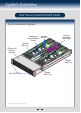
System Overview Intel® Server System H2000JF Family System Features and Components Common Redundant Power Supply Compute Upper/Lower Power Distribution Node 3 Tray Boards Compute Node 1 Tray C LO S E 1s t O P EN 1s t C LO S E 1s t O P EN 1s t C LO S E 1s t O P EN 1s HDD bays with Hot Swap Backplane t C LO S E C 1s LO t S E 1s t O P EN P t O 1s EN 1s t C LO S E 1s t O P EN 1s t C LO S E 1s t O P EN 1s t C LO S E 1s t O P EN 1s t Compute Node 2 Tray Front Control Panel * 3.
System Overview Intel® Server System H2000WP Family System Features and Components Upper/Lower Power Distribution Boards Compute Node 3 Tray Common Redundant Power Supply Compute Node 1 Tray HDD bays with Hot Swap Backplane Compute Node 4 Tray Compute Node 2 Tray Front Control Panel * 3.5" Hard Drive Bay system as shown Intel® Server System H2000JF and H2000WP Hard Drive Numbering Diagram 12X3.
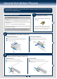
General Installation Process The installation instructions in this section are for common components of Intel® Server System H2000JP and H2000WP family. 1 Minimum Hardware Requirements To avoid integration difficulties and possible board damage, your system must meet the following minimum requirements: Preparing the System Observe normal ESD (Electrostatic Discharge) procedures. • Processor: Intel® Xeon® processor E5-2600 product family (TDP 130W or below).
General Installation Process The installation instructions in this section are for common components of Intel® Server System H2000JP and H2000WP family. 4 Remove/Install Node Tray Air Duct B Removing the Air Duct A Press and hold both left and right side of rear air duct (see letter “A”). B Lift the rear end of the air duct slowly (see letter “B”). Rotate the airduct to more than 45 degrees up, and pull it out.
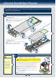
General Installation Process 6 Install the Processor(s) A. Open the Socket Lever B. Open the Load Plate A Push down the lever handle on the OPEN 1st side and away from the socket to release it. A Press the locking lever slightly to raise the load plate . B Repeat the steps to release the lever on the other side. B Open the load plate all the way. C LO S E 1s t OS E 1s t RE M OV E P EN EN OP O 1s t A O P EN RE M OV E t 1s A CL NOTE: Release the levers in the order as shown.
General Installation Process 7 8 Install Processor Heatsink(s) CAUTION: The heatsink has thermal interface material (TIM) on the underside of it. Use caution so that you do not damage the thermal interface material. Use gloves to avoid sharp edges. CPU socket 1 heat sink is different from CPU socket 2 heat sink. In the Server System H2000JF family, FXXCA90X90HS is for CPU socket 1 and FXXEA90X90HS is for CPU socket 2.
General Installation Process Install Memory Modules ... Continued To Install DIMMs: Open both DIMM socket levers. C Insert DIMM making sure the connector edge of the DIMM aligns correctly with the slot. D Push down firmly on the DIMM until it snaps into place and both levers close. E IMPORTANT! Visually check that each latch is fully closed and correctly engaged with each DIMM edge slot. C E CAUTION: Avoid touching contacts when handling or installing DIMMs. A B Note location of alignment notch.
General Installation Process Install Hard Drives ... Continued 3.5" Hard Drive Carrier (For system with 3.5" hard drive bay only) Remove the drive carrier by pressing the green button and opening the lever. B Slide the carrier out. C Remove the four screws securing the HDD interface bracket and remove the HDD interface bracket. TO P AB G F T TIN E OF OU IV K M DR EA RE RD BR EFO HA B 5´´ 2. A AB NG F T TI E OF OU IV K M DR EA RE RD BR EFO HA B 5´´ 2.
General Installation Process 12 1 Install I/O Module Riser and Carrier Assembly on Riser Slot 2 3 Install Riser to riser bracket. 4 Attach IOM bracket to IOM carrier (see letter “D”), and then plug-in the IOM assembly into the riser slot. (See letter “C”) Install I/OM assembly and add-in card assembly (if any) using screws. (See letters “F”, “E”, and “G”) C 2 Install I/O Module to I/OM Carrier and fasten with screw.
General Installation Process 15 16 Remove the Top Cover A B Remove four screws. Lift the cover upwards from B edge and pull to detach the latches. Install Top Cover A Place system cover onto the chassis and engage recessed edge at rear of cover. B Put down the cover from B edge and tighten the screw at front. A A B B Note: Before removing the top cover, turn off all peripheral devices connected to the server, turn off the server, and disconnect the power cord.
General Installation Process Intel® Server Chassis H2000 Assembly and Disassembly 18 Assembling the Server System with Server Chassis H2000 B. Inserting the Node Tray Node Dummy Tray Bo r d Se ar A. Removing the Node Dummy Tray Latch Always keep dummy trays in all empty node slots for thermal purpose. S Boaerver rd S Boaerver rd Ser Boa ver rd S Boaerver rd * 3.5" Hard Drive Bay system as shown 19 Removing a Node Tray from a Chassis B. Inserting the Dummy Tray back Bo er rv d Se ar A.
Reference Intel® Server Board S2600JF Component Layout A B C D E F G H I J K L M N O P Q R S T U AD AC AB AA Z Y X U. NIC Port 1 V. Riser Slot1 with PCIe Gen3 x16 W. Integrated BMC X. Storage Upgrade key Y. SATA port 1 Z. PCH C600 AA. CPU 1 AB. XDP connector AC. CPU 2 AD. 2x3 PWR connector (2 total) K. RMM4 lite L. POST and QSFP LED M. QSFP N. USB x2 O. Debug connector P. Status & ID LED Q. VGA out R. Dual port 1Gbe NIC S. NIC Port 2 T. Serial Port A A. 2x7 fan control connector B.
Reference Front Panel Controls and Indicators Standard Control Panel Your system may include one of two front control panel types.The features of each are as follows: A. System Power Button with LED B. System ID Button C. System Status LED D.
Reference Cable Routing inside Server System H2000WP Node Tray Yellow Lines: Fan cable connection Red Line: Mother board power cable connection Blue line: Fan control signal cable connection Optional Accessories Product Code MM# HNS2600WP 918378 HNS2600WPQ 918377 HNS2600WPF 921314 H2312XXJR H2216XXJR H2312XXKR H2216XXKR AXXRMM4IOMW 919020 919021 919022 919023 918304 Description Intel Server Board S2600WP; Intel Node Power Board; Intel Bridge Board; 1U PCI Express Low Profile Riser; 1U Cu/Al 84m
Reference Intel® Sever System RAID Options Step 1 Step 2 Choose a RAID Option Choose proper Motherboard RAID Options On-Server board AHCI Capable SATA Controller (SATA Ports) Supported RAID option: 1. Intel® RSTe 2. Intel® ESRT2 Enable RAID Option hardware Intel® RAID C600 Upgrade Keys 1. During system post, press F2 to enter System BIOS Setup Refer to the key description table on previous page to populate a proper key on your system. 2.
G54451-002