Intel® Server Chassis H2000 Family Service Guide A Guide for Technically Qualified Assemblers of Intel® Identified Subassemblies/Products Order Number: G59060-001
Disclaimer Disclaimer Information in this document is provided in connection with Intel® products. No license, express or implied, by estoppel or otherwise, to any intellectual property rights is granted by this document.
Safety Information Safety Information Important Safety Instructions Read all caution and safety statements in this document before performing any of the instructions. See also Intel® Server Boards and Server Chassis Safety Information on the Intel® Server Deployment Toolkit 3.0 CD and/or at http://www.intel.com/support/motherboards/server/sb/cs-010770.htm. Wichtige Sicherheitshinweise Lesen Sie zunächst sämtliche Warnund Sicherheitshinweise in diesem Dokument, bevor Sie eine der Anweisungen ausführen.
Warnings Warnings Heed safety instructions: Before working with your server product, whether you are using this guide or any other resource as a reference, pay close attention to the safety instructions. You must adhere to the assembly instructions in this guide to ensure and maintain compliance with existing product certifications and approvals. Use only the described, regulated components specified in this guide.
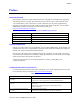
Preface Preface About this Manual This manual is written for system technicians who are responsible for troubleshooting, upgrading, and repairing this server system. This document provides a brief overview of the features of the server board/chassis, a list of accessories or other components you may need, troubleshooting information, and instructions on how to add and replace components on the Intel® Server Chassis H2000 family products. For the latest revision of this manual, go to http://www.intel.
Preface For this information or software Use this Document or Software ® Intel Server Configurator Tool For server configuration guidance and compatibility To be provided later. For system power budget guidance Power Budget Analysis Tool To be provided later. ® For software to manage your Intel Server System. For system firmware updates and onboard device drivers Intel® Server Management Software See the section on the web page titled, “Software/Code”.
Table of Contents Table of Contents Safety Information ..................................................................................................................................... iii Preface.......................................................................................................................................................... v 1 Server System Features........................................................................................................................
Table of Contents Appendix A: Technical Reference ........................................................................................................... 29 Power Supply Input Voltages ..................................................................................................... 29 Power Supply Output Voltages .................................................................................................. 29 System Environmental Specifications ..................................................
List of Figures List of Figures Figure 1. Intel® Server Chassis H2000 Family (H2312xx as demonstrated) ................................................ 1 Figure 2. Intel® Server Chassis H2000 Overview (H2312xx as Demonstrated)........................................... 2 Figure 3. Front View of Intel® Server Chassis H2312xx with 12x3.5" HDD bays ...................................... 3 Figure 4. Front View of Intel® Server Chassis H2216xx with 16x2.5" HDD bays ......................................
List of Figures Figure 48. Installing the Chassis to Rack .................................................................................................... 27 Figure 49. Extending Slides before Chassis Removal ................................................................................ 28 Figure 50. Removing the Chassis from Rack .............................................................................................
List of Tables List of Tables Table 1. Intel® Server Chassis H2000 family product list ............................................................................ v Table 2. Server Chassis References .............................................................................................................. v Table 3. Intel® Server Chassis H2000 Feature Summary ............................................................................. 1 Table 4. CRPS Input Voltage.....................................
Server System Features 1 Server System Features This chapter briefly describes the main features of the Intel® Server Chassis H2000 family. This includes illustrations of the products, a list of the server system features, and diagrams showing the location of important components and connections on the server systems. Figure 1. Intel® Server Chassis H2000 Family (H2312xx as demonstrated) Server System Feature Overview Table 3 sumarizes the features of the the server systems. Table 3.
Server System Features Feature Description 1600w AC Common Redundant Power Supply (CRPS), 80 plus Platinum with PFC, supporting CRPS configuration. Chassis SKU: H2312xxKR, H2216xxKR. 12x 3.5-inch SATA/SAS HDD bays (SKU: H2312xx). 16x 2.5-inch SATA/SAS HDD bays (SKU: H2216xx). Storage Bay Options Available Rack Mount Kit Options Basic slide rail kit, bundled with system package. Server Chassis Parts This section helps you identify the components of your server system.
Server System Features Figure 3. Front View of Intel® Server Chassis H2312xx with 12x3.5" HDD bays Figure 4. Front View of Intel® Server Chassis H2216xx with 16x2.5" HDD bays The Compute Node in the chassis has dedicated numbering by position. Figure 5. Rear View of Intel® Server Chassis H2000 with Power Supply Unit Each Compute Node has dedicated Hard Disk Drive array based on backplane controller design. Below are schemes for HDD array in correspondent to Compute Node. Figure 6.
Server System Features Figure 7. HDD array scheme on Intel® Server Chassis H2216xx Front Panel The system contains two sets of control panels on left and right rack handles. Each control panel contains two sets of control buttons and LEDs for each Compute Node. Below is the scheme of control panel. A B C D System Power Button with LED System ID LED Button System Status LED NetworkLink/Activity LED Figure 8.
Server System Features Hot-Swap SAS/SATA Backplane The Hot-Swap SAS/SATA backplane serves as an interface between the mother board and the system drives. The following diagrams show the location for each connector found on the backplane. 12 x 3.5-inch Hard Drive Backplane A SATA/SAS connectors for Node 1 B SATA/SAS connectors for Node 2 C SATA/SAS connectors for Node 3 D SATA/SAS connectors for Node 4 Figure 10. 12 x 3.
Server System Features N 2x40 pin Bridge Board connector for Node 2 O 2Blade Compute Node Power connector for Node 2 Figure 11. 12 x 3.5-inch Hard Drive Backplane Components (Rear View) 16 x 2.5-inch Hard Drive Backplane A SATA/SAS connectors for Node 1 B SATA/SAS connectors for Node 2 C SATA/SAS connectors for Node 3 D SATA/SAS connectors for Node 4 Figure 12. 16 x 2.
Server System Features N 2Blade Compute Node Power connector for Node 2 O 20-pin Front Panel cable connector for Node 2, 4 Figure 13. 16 x 2.5-inch Hard Drive Backplane Components (Rear View) Dummy Tray Cover The Dummy tray cover is shipped together with chassis. It must be removed before installing computing node tray, or it must be restored if the compute node tray is empty. Dummy Tray Cover Figure 14.
Hardware Installations and Upgrades 2 Hardware Installations and Upgrades Before You Begin Before working with your server product, pay close attention to the Safety Information at the beginning of this manual. Note: Whenever you service the system, you must first power down the server and unplug all peripheral devices and the AC power cord.
Hardware Installations and Upgrades Removing and Installing the Front Bezel Removing the Front Bezel If your system includes a front bezel, follow these steps to remove the front bezel: 1. Unlock the bezel if it is locked. 2. Remove the left end of front bezel from rack handle (see letter A). 3. Rotate the front bezel anticlockwise to release the latches on the right end from the rack handle (see letter B). Figure 15.
Hardware Installations and Upgrades Removing and Installing the Chassis Top Cover Removing the Chassis Top Cover The server Chassis must be operated with the top cover in place to ensure proper cooling. You will need to remove the top cover to add or replace components (backplane, main power cables, power distribution board) inside of the chassis. Before removing the top cover, power down the server and unplug all peripheral devices and the power cable(s).
Hardware Installations and Upgrades Figure 18. Installing the System Cover Removing and Installing the Compute Node Tray Each Compute Node tray is identical in the chassis. They are designed for either “cold” or “hot” swappable. The Node Tray can only be plugged from rear chassis. Installing the Node Tray 1. Remove the dummy tray cover. Figure 19.
Hardware Installations and Upgrades 2. Align and slide in the Node Tray to the chassis rail. 3. Push the Node Tray along the rail until the latch locks in position with a “tick”. Figure 20. Installing the Node Tray Removing the Node Tray 1. Carefully push the latch in, on the left hand side of the Node Tray. 2. Pull the handle with the Node Tray while still pressing the latch.
Hardware Installations and Upgrades Figure 21. Pulling out the Node Tray 3. Restore the Dummy Tray Cover. Figure 22. Restore the Dummy Tray Cover Removing and Installing the Redundant Power Supply Unit The system equipped with two CRPS for redundancy. Each of them can be hot swappable. Removing the Power Supply Unit 1. Carefully push in the latch on the right hand of PSU. 2. Pull the handle with the PSU while still press the latch.
Hardware Installations and Upgrades Figure 23. Removing the PSU Installing the Power Supply Unit 1. Align and slide in the PSU to the power cage rail. 2. Push the PSU along the rail until the latch locks in position with a “tick”. Figure 24. Installing the PSU Installing and Removing Hot-swap Hard Drive Caution: If you don't install all drives, empty drive bays must be occupied by carriers with plastic drive blank provided to maintain proper system cooling. Installing a Hard Disk Drive into 3.
Hardware Installations and Upgrades Figure 25. Installing Hard Disk Drive – installing 3.5" HDD to carrier 2. With the lever open, insert the hard disk drive assembly into the chassis (see letter A). Push in the lever to lock it into place (see letter B). Figure 26. Installing Hard Disk Drive – Inserting 3.5" HDD assembly Installing a Hard Disk Drive into 2.5" Hard Drive Carrier 1. Remove the four screws securing the plastic drive blank from the 2.5" HDD carrier and install the 2.
Hardware Installations and Upgrades Figure 27. Installing Hard Disk Drive – Installing 2.5" HDD to carrier 2. With the lever open, insert the hard disk drive assembly into the chassis, then push in the lever to lock it into place (see letter F). Figure 28. Installing Hard Disk Drive – Inserting 2.5" HDD assembly Installing and Removing the 2.5" Backplane Board Removing the 2.5" Backplane board 1. Disconnect all cables from the backplane board. 2.
Hardware Installations and Upgrades 3. Straightly lift up the backplane board to remove from the chassis holder. Figure 29. Removing the 2.5" backplane board Installing the Server Board 1. Place the backplane board into the clamps on chassis base. Figure 30. Align the backplane to the clamps on the chassis base 2. Secure the backplane board with four screws (see letter B).
Hardware Installations and Upgrades Figure 31. Installing the 2.5" backplane board 3. Reconnect all cables to the backplane. Installing and Removing the 3.5" Backplane Board Removing the 3.5" Backplane board 1. Disconnect all cables from the backplane board. 2. Remove the three screws to release the backplane board from chassis. 3. Straightly lift up the backplane board to remove from the chassis holder.
Hardware Installations and Upgrades Figure 32. Removing the 2.5" backplane board Installing the Server Board 1. Place the backplane board into the clamps on chassis base. Figure 33. Align the backplane to the clamps on the chassis base 2. Secure the backplane board with three screws (see letter B).
Hardware Installations and Upgrades Figure 34. Installing the 2.5" backplane board 3. Reconnect all cables to the backplane. Installing and Removing the Power Distribution Board Removing the PDB 1. Remove top cover and power supply units from chassis. 2. Remove power cables and PMBus cable between PDB and backplane. 3. Release the four screws of upper PDB board and remove it.
Hardware Installations and Upgrades Figure 35. Removing the upper PDB 4. Release the four screws of lower PDB board and remove it. Figure 36. Removing the lower PDB Installing the PDB 1. Remove top cover and power supply units from chassis. 2. Install the lower PDB first and secure with four screws.
Hardware Installations and Upgrades Figure 37. Installing the lower PDB 3. Connect the power cables and PMBus cable to lower PDB. 4. Install the upper PDB and scure with four screws. Figure 38. Installing the upper PDB 5. Connect power cables and PMBus cable to upper PDB.
Hardware Installations and Upgrades 6. Close top cover and install power supply units. Replacing the Front Control Panel board Removing the Front Control Panel 1. Loose and remove four screws on the back of handle. Be careful of the control panel cable on the back. Figure 39. Removing FP Assembly from Rack Handle 2. Disconnect the cable from the control panel board. Figure 40. Disconnecting Control Panel Cable 3.
Hardware Installations and Upgrades Figure 41. Removing Control Panel Board Installing Front Control Panel Board 1. Install front control panel board to panel shell. Figure 42. Installing Control Panel Board 2. Connect cable to front panel board.
Hardware Installations and Upgrades Figure 43. Connecting Cable to Front Panel Board 3. Install front control panel assembly to chassis handle. Figure 44. Installing Control Panel Assembly to Rack Handle Rack Mounting the Chassis Mounting the Chassis to Rack The slide rail kit, which is bundled with Intel® Server System H2000JF family is packed in the same shipping box together with the chassis.
Hardware Installations and Upgrades 1. Preparation before slide installation. Figure 45. Removing Inner Member from Slides 2. Install slides to rack. Figure 46.
Hardware Installations and Upgrades 3. Install inner members to chassis. Figure 47. Installing Inner Member to Chassis 4. Install chassis to fixed slides. Figure 48. Installing the Chassis to Rack Removing the Chassis from Rack Following the below steps to remove the chassis from Rack. 1. Extend slides.
Hardware Installations and Upgrades Figure 49. Extending Slides before Chassis Removal 2. Remove Inner Member from Chassis. Figure 50.
Appendix A: Technical Reference Appendix A: Technical Reference Power Supply Input Voltages Table 4. CRPS Input Voltage Parameter Min Rated Max Start up VAC Power Off VAC 110VAC 90 Vrms 100-127 Vrms 140 Vrms 85 VAC± 4VAC 70VAC±5VAC 220VAC Frequency 180 Vrms 47 Hz 200-240 Vrms 50/60 Hz 264 Vrms 63 Hz Power Supply Output Voltages Table 5. CRPS Output Voltage Parameter Min Nom Max Unit Tolerance +12VSTB +11.40V +12.000V +12.60V Vrms ±5% +12V +11.40V +12.000V +12.
Appendix A: Technical Reference Parameter Limits Shock, packaged Non-palletized free fall in height 18 inches (80 lbs to < 100 lbs) Vibration, unpackaged 5 Hz to 500 Hz, 2.20 g RMS random ESD +/-12 KV except I/O port +/- 8 KV per Intel® Environmental Test Specification.
Appendix B: Regulatory and Compliance Information Appendix B: Regulatory and Compliance Information Please refer to the Server Products Regulatory and Safety document for the product regulatory compliance reference. The document can be downloaded from http://www.intel.com/p/en_US/support/server/.
Appendix C: Getting Help Appendix C: Getting Help If you encounter an issue with your server system, follow these steps to obtain support: 1. Visit the following Intel® support web page at http://www.intel.com/p/en_US/support/server/. This web page provides 24x7 support when you need it to get the latest and most complete technical support information on all Intel® Enterprise Server and Storage Platforms.
Appendix D: Intel® Server Issue Report Form Appendix D: Intel® Server Issue Report Form Issue Report Form (Rev 3.6) Note: Filling out this form completely is required for any escalation. Customer Contact Information: Customer Support Case#: Intel® Server Board or System: (Example: S2600JF, H2216JF/H2312JF) Server Chassis: (Example P4000M. If third-party chassis used, indicate make and model.
Appendix D: Intel® Server Issue Report Form Processor information: Type Speed Spec Thermal Solution Processor 1 Processor 2 Processor 3 Processor 4 Thermal solution (Heat sink) examples: (1U, Passive w/air ducting, Active w/fan, and so on) Memory: Manufacturer Part Number On Intel® tested list? DRAM Part Number Add-in adapters (Example: NICs, Management Adapters, Serial Expansion Cards, PCIExpress* Adapters, RAID Controllers, SCSI Controllers, and so on): Type Slot Manufacturer Model Firmware
Appendix D: Intel® Server Issue Report Form Description/Use Manufacturer Model Firmware Storage Devices (Example: SCSI, SATA, SAS, USB, Tape, and so on): Manufacturer Model Type Size Firmware In Hot Swap Bay? Operating System Information (Example: RedHat* Enterprise Linux, Microsoft Windows Server 2003*, Service Pack 1, OEM CD): Manufacturer: Version: Language version (English, Arabic, and Chinese (Simplified)): Service Pack Level or Kernel Revision: Distribution (OEM/Retail): Intel® RAID Contro
Appendix D: Intel® Server Issue Report Form Detailed description of issue: Troubleshooting tried: Steps to replicate the issue: 36 ® Intel Server System H2000JF Family Service Guide
Appendix D: Intel® Server Issue Report Form Issue impact statements: Do you have any potential Intel® system, or component purchases that this issue is holding up? If yes, please provide a brief description below. Do you have systems already purchased that are not being delivered to your customers because of this issue? If yes, please provide a brief description below.