
Technical Product Specification


Product Architecture Overview Intel
®
Server
Board S2600WP TPS
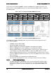
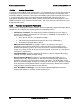
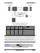
Figure 12. PCI Express* Lane distribution scheme
Table 9. CPU1 and CPU2 PCIe Connectivity
CPU
Port
IOU
Width
Connection
CPU1
DMI2
IOU2
x4
PCH (lane reversal, no polarity inversion)
CPU1
PE1
IOU2
X8
QDR/FDR InfiniBand*
CPU1
PE2
IOU0
x16
Riser 1
CPU1
PE3
IOU1
x16
Riser 2 (x8 for IOM on Riser)
CPU2
DMI2
IOU2
x4
Unused
CPU2
PE1
IOU2
x8
Unused
CPU2
PE2
IOU0
x16
Riser 3
CPU2
PE3
IOU1
x16
Riser 4
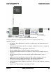
Note: Riser Slot 3 and slot 4 can only be used in dual processor configurations. With dual
processor configurations, there is still an add-in graphic card in the PCI slot, the default video
output is still from on-board integrated BMC until the users enable “dual monitor Video” in BIOS.
Users need to determine whether Legacy VGA video output is enabled for PCIe slots attached
to Processor Socket 1 (PCIe slot 1 and slot 2) or 2 (PCIe slot 3 and slot 4). Socket 1 is the
default. You can change “legacy VGA socket” in BIOS setup interface from default “CPU socket
1” to “CPU socket 2” to enable video output through add-in graphic card which is in Riser slot 3
or 4.
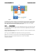
Onboard Video
Enabled / Disabled
Legacy VGA Socket
CPU Socket 1/CPU Socket 2
Dual Monitor Video
Enabled / Disabled
Figure 13. Legacy VGA Socket configuration in BIOS
Intel order number G44057-007 Revision 1.6
22