
Technical Product Specification


Intel
®
Light-Guided Diagnostics Intel
®
Server Board S2600WP TPS
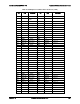
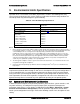
Table 88. Network link/activity LED
LED
Color
Condition
What It Means
LAN – Link/Activity
Green
On
LAN link/no access
Green
Blink
LAN access
Off
Idle
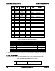
8.1.4
Dedicated InfiniBand* Link/Activity LED
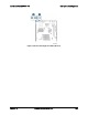
The server board provides dedicated LEDs for InfiniBand* Link/Activity. They are located on the
baseboard rear, near diagnostic LED set. This set of LEDs only works on S2600WPQ
baseboard. See block B in Figure 57 for the location of LEDs.
The following table shows the LED details:
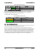
Table 89. InfiniBand* link/activity LED
LED Color
LED State
NIC State
Amber (Right)
Off
No Logical Link
Blinking
Logical Link established
Green (Left)
Off
No Physical Link
On
Physical Link established
8.2
POST Code Diagnostic LEDs
Eight amber POST code diagnostic LEDs are located on the back left edge of the server board
in the rear I/O area of the server board by the QSFP connector.
During the system boot process, the BIOS executes a number of platform configuration
processes, each of which is assigned a specific hex POST code number. As each configuration
routine is started, the BIOS displays the given POST code to the POST code diagnostic LEDs
on the back edge of the server board. To assist in troubleshooting a system hang during the
POST process, you can use the Diagnostic LEDs to identify the last POST process executed.
For a complete description of how these LEDs are read and a list of all supported POST codes,
refer to Appendix D. (Table 89 refers to InfiniBand* LEDs for Link and activity status.)
Intel order number G44057-007 Revision 1.6
164