
Technical Product Specification


Intel
®
Server
Board S2600WP TPS Connector/Header Locations and Pin-out
7.10.8
USB Connectors
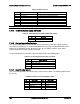
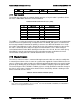
The following table details the pin-out of the external stack USB port 0/1 connectors (J3A1)
found on the back edge of the server board.
Table 83. External USB port Connector (J3A1)
Pin
Signal Name
Description
1
+5V
USB Power
2
USB_N
Differential data line paired with DATAH0
3
USB_P
Differential date line paired with DATAL0
4
GND
Ground
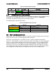
One 2x5 connector on the server board provide an option to support two additional internal USB
port (USB 2/3). The pin-out is detailed in the following table:
Table 84. Internal USB Connector (J2D1)
Pin
Signal Name
Pin
Signal Name
1
+5V
2
+5V
3
USB_N
4
USB_N
5
USB_P
6
USB_P
7
GND
8
GND
9
Key Pin
10
NC
7.10.9
QSFP for InfiniBand*
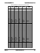
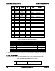
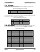
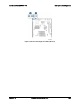
The following table details the pin-out of the QSFP connector (J2B1) found on the back edge of
the server board. This port is only available on board SKU S2600WPQ and S2600WPF.
Table 85. QSFP Pin Definition
Side A
Signal
Side B
Signal
1
GND
1
GND
2
IB_RX0_DN0
2
IB_RX0_DN1
3
IB_RX0_DP0
3
IB_RX0_DP1
4
GND
4
GND
5
IB_RX0_DN2
5
IB_RX0_DN3
6
IB_RX0_DP2
6
IB_RX0_DP3
7
GND
7
GND
8
SMB_IB_QSFP0_DATA
8
QSFP0_MODPRSL_N
9
SMB_IB_QSFP0_CLK
9
IRQ_QSFP0_N
10
P3V3_RX_PORT0
10
P3V3_TX_PORT0
11
RST_QSFP0_N
11
P3V3_PORT0
12
FM_QSFP0_MODSEIL_N
12
QSFP0_LPMODE
13
GND
13
GND
14
IB_TX0_DP3
14
IB_TX0_DP2
15
IB_TX0_DN3
15
IB_TX0_DN2
16
GND
16
GND
17
IB_TX0_DP1
17
IB_TX0_DP0
18
IB_TX0_DN1
18
IB_TX0_DN0
Revision 1.6 Intel order number G44057-007
161