
Technical Product Specification

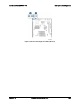

Connector/Header Locations and Pin-out Intel
®
Server
Board S2600WP TPS
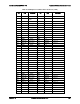
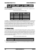
Table 79. SATA Connector
Pin
Signal Name
Description
1
GND
Ground
2
SATA_TX_P
Positive side of transmit differential pair
3
SATA_TX_N
Negative side of transmit differential pair
4
GND
Ground
5
SATA_RX_N
Negative side of receive differential pair
6
SATA_RX_P
Positive side of receive differential pair
7
P5V_SATA/GND
+5V for DOM or Ground for SATA signals
Note: SATA DOM requires external power cannot be used with SATA-1 port.
7.10.5
Hard Drive Activity (Input) LED Header
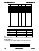
Table 80. SATA HDD Activity (Input) LED Header (J6C5)
Pin
Description
1
LED_HD_ACTIVE_L
2
NC
7.10.6
Storage Upgrade Key Connector
The server board provides one SATA/SAS storage upgrade key connector (J6C4) on board.
The Storage Upgrade Key is a small PCB board that has up to two security EEPROMs that are
read by the system ME to enable different versions of LSI* RAID 5 software stack and/or
upgrade from SATA to SAS storage functionality.
The pin configuration of connector is identical and defined in the following table.
Table 81. Storage Upgrade Key Connector (J6C4)
Pin
Signal Description
1
GND
2
DYN_SKU_KEY
3
GND
4
SAS_SATA_RAID_KEY
7.10.7
Serial Port Connectors
The server board provides one internal 9-pin serial A header (J6A2). The following tables define
the pin-outs.
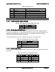
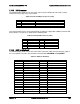
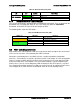
Table 82. Internal 9-pin Serial A
(COM1) (J6A2)
Pin
Signal Name
Pin
Signal Name
1
SPB_DCD
2
SPB_DSR
3
SPB_SIN_N
4
SPB_RTS
5
SPB_SOUT_N
6
SPB_CTS
7
SPB_DTR
8
SPB_RI
9
GND
Intel order number G44057-007 Revision 1.6
160