
Technical Product Specification


Connector/Header Locations and Pin-out Intel
®
Server
Board S2600WP TPS
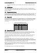
State
LED State
Identify active through command
~1 Hz blink
Off
Off
There is no precedence or lock-out mechanism for the control sources. When a new request
arrives, all previous requests are terminated. For example, if the chassis ID LED is blinking and
the chassis ID button is pressed, then the chassis ID LED changes to solid on. If the button is
pressed again with no intervening commands, the chassis ID LED turns off.
7.10
I/O Connectors
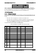
7.10.1
PCI Express* Connectors
The Intel
®
Server Board S2600WP uses four PCI Express* slots physically with different pin-out
definition. Each riser slot has dedicated usage and cannot be used for normal PCIe based add-
in card.
Riser Slot 1: Riser to support PCIe x16 add-in card or GPGPU card
Riser Slot 2: Riser to support PCIe x16 add-in card, GPGPU card or Intel
®
IOM card
Riser Slot 3 and 4: Risers to support PCIe x16 add-in cards or GPGPU cards (Intel
®
server system H2000WP does not support risers for slot 3 and slot 4.)
The pin-outs for the slots are shown in the following tables.
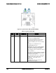
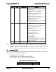
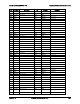
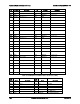
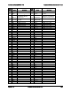
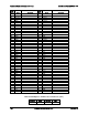
Table 72. PCI Express* x16 IO Riser Slot 1 Connector (J6A1)
Pin
Pin Name
Description
Pin
Pin Name
Description
B1
12V
20W 3.3V generated on
riser
A1
12V
20W 3.3V generated on
riser
B2
12V
66W for GPU
A2
12V
66W for GPU
B3
12V
66W for GPU
A3
12V
66W for GPU
B4
12V
66W for GPU
A4
SMDATA
B5
SMCLK
A5
3.3VAUX
For wake on LAN
B6
3.3VAU
X
For wake on LAN
A6
GPU_NODE_
ON
can turn of 2U GPU
power
B7
GND
A7
GPU_PWRGD
B8
Tach9
A8
Tach11
B9
Tach8
A9
Tach10
B10
Tach7
A10
Tach6
B11
Spare
A11
Spare
KEY
B12
Spare
A12
PWM2
GPU Fan speed control
B13
Spare
A13
GND
B14
GND
A14
PERST#
B15
SMBUS
_R4
CLK
A15
WAKE#
B16
SMBUS
_R4
DAT
A16
GND
Intel order number G44057-007 Revision 1.6
150