
Technical Product Specification


Intel
®
Server
Board S2600WP TPS Connector/Header Locations and Pin-out
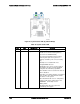
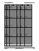
Color
State
System Status
Description
Amber
~1 Hz blink
Non-Fatal
Non-fatal alarm – system is likely to fail:
BIOS Detected
In non-mirroring mode, if the threshold of ten
correctable errors is crossed within the
window.
1
PCI Express* uncorrectable link errors.
Integrated BMC Detected.
Critical threshold crossed – Voltage,
temperature, power nozzle, power gauge, and
PROCHOT (therm Ctrl) sensors.
VRD Hot asserted.
A minimum number of fans to cool the system
is not present or have failed.
Amber
Solid on
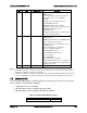
Fatal
Fatal alarm – system has failed or shut down:
BIOS Detected.
DIMM failure when there is one DIMM present
and no good memory is present.
1
Run-time memory uncorrectable error in non-
redundant mode.
1
CPU configuration error (for instance,
processor stepping mismatch).
Integrated BMC Detected.
CPU CATERR signal asserted.
CPU 1 is missing.
CPU THERMTRIP.
No power good – power fault.
Power Unit Redundancy sensor – Insufficient
resources offset (indicates not enough power
supplies are present).
Off
N/A
Not ready
Main power off
Notes:
1. The BIOS detects these conditions and sends a Set Fault Indication command to the Integrated BMC to
provide the contribution to the system status LED.
2. Support for an upper, non-critical threshold limit is not provided in default SDR configuration. However if a
user does enable this threshold in the SDR, then the system status LED should behave as described.
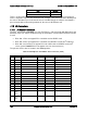
7.9
Chassis ID LED
The chassis ID LED provides a visual indication of a system being serviced. The state of the
chassis ID LED is affected by the following:
Toggled by the chassis ID button
Controlled by the Chassis Identify command (IPMI)
Controlled by the Chassis Identify LED command (OEM)
Table 71. Chassis ID LED Indicator States
State
LED State
Identify active through button
Solid on
Revision 1.6 Intel order number G44057-007
149