
Technical Product Specification

Connector/Header Locations and Pin-out Intel
®
Server
Board S2600WP TPS
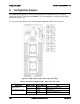
7. Connector/Header Locations and Pin-out
7.1
Power Connectors
To facilitate customers who want to cable to this board from a power supply, the power
connector is implemented through two 6-pin Minifit Jr* connectors, that can be used to deliver
12amps per pin or 60+Amps total.
Note that no over-voltage protective circuits will exist on
the board.
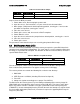
Table 65. Main Power Supply Connector 6-pin 2x3 Connector (J4K1 and J3K1)
Pin
Signal Name
Pin
Signal Name
1
GND
4
+12V
2
GND
5
+12V
3
GND
6
+12V
7.2
System Management Headers
7.2.1
Intel
®
Remote Management Module 4 (Intel
®
RMM4 Lite) Connector
A 7-pin Intel
®
RMM4 Lite connector (J1A2) is included on the server board to support the
optional Intel
®
Remote Management Module 4. There is no support for third-party management
cards on this server board.
Note: This connector is not compatible with the Intel
®
Remote Management Module 3
(Intel
®
RMM3).
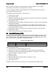
Table 66. Intel
®
RMM4 Lite Connector Pin-out (J1A2)
Pin
Signal Description
Pin
Signal Description
1
DI
2
VCC
3
CLK
4
KEY
5
GND
6
DO
7
GND
8
CS_N
7.2.2
IPMB Header
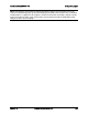
Table 67. IPMB Header 4-pin (J2D2)
Pin
Signal Name
Description
1
SMB_IPMB_5VSB_DAT
BMC IPMB 5V standby data line
2
GND
Ground
3
SMB_IPMB_5VSB_CLK
BMC IPMB 5V standby clock line
4
P5V_STBY
+5V standby power
7.3
Bridge Board Connector
The bridge board delivers SATA/SAS signals, Disk back plane management signals, BMC
SMBus*’s as well as SSI-Compliant front panel and miscellaneous Node specific signals.
The
fifth SAS connection was added to support a Raid 5 + hot spare configuration.
This drives the
addition of a second set of SGPIO pins.
Intel order number G44057-007 Revision 1.6
144