
Technical Product Specification


Intel®
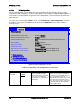
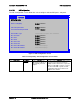
Server Board S2600WP TPS BIOS Setup Interface
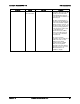
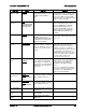
Setup Item
Options
Help Text
Comments
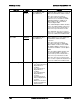
Memory Mapped
I/O above 4GB
Enabled
Disabled
Enable or disable memory
mapped I/O of 64-bit PCI devices
to 4 GB or greater address
space.
When enabled, PCI/PCIe Memory
Mapped I/O for devices capable of 64-
bit addressing is allocated to address
space above 4GB, in order to allow
larger allocations and avoid impacting
address space below 4GB.
Memory Mapped
I/O Size
Auto
1G/2G/4G/8G/16G/
32G/64G/128G/25
6G/512G/1024G
Sets MMIO Size: Auto
When Memory Mapped I/O above 4GB
option enabled, this option sets the
preserved MMIO size as PCI/PCIe
Memory Mapped I/O for devices
capable of 64-bit addressing. This
option is grayed out when Memory
Mapped I/O above 4GB option is
disabled.
Onboard Video
Enabled
Disabled
Onboard video controller.
Warning: System video is
completely disabled if this option
is disabled and an add-in video
adapter is not installed.
When disabled, the system requires an
add-in video card in order for the video
to be seen.
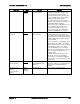
Legacy VGA
Socket
CPU Socket 1
CPU Socket 2
Determines whether Legacy
VGA video output is enabled for
PCIe slots attached to Processor
Socket 1 or 2. Socket 1 is the
default.
This option is necessary when using an
add-in video card on a PCIe slot
attached to CPU Socket 2, due to a
limitation of the processor IIO. The
Legacy video device can be connected
through either socket, but there is a
setting that must be set on only one of
the two. This option allows the switch
to using a video card in a slot
connected to CPU Socket 2.
Dual Monitor
Video
Enabled
Disabled
If enabled, both the onboard
video controller and an add-in
video adapter are enabled for
system video. The onboard video
controller becomes the primary
video device.
This option must be enabled to use an
add-in card as a secondary POST
Legacy Video device while also
displaying on the Onboard Video
device.
If there is no add-in video card in any
PCIe slot connected to CPU Socket 1,
this option is set to Disabled and
grayed out and unavailable.
NTB PCIe Port on
CPU Socket 1
Transparent
Bridge/
NTB to NTB/NTB
to RP
Configure CPU PCIe root port 3A
as transparent bridge, or NTB to
NTB, or NTB to Root Port.
Default is Transparent Bridge.
NTB PCIe Port on
CPU Socket 2
Transparent
Bridge/
NTB to NTB/NTB
to RP
Configure CPU PCIe root port 3A
as transparent bridge, or NTB to
NTB, or NTB to Root Port.
Default is Transparent Bridge.
NIC Configuration
View/Configure NIC information
and settings.
UEFI Network
Stack
View/Configure UEFI Network
Stack Settings.
UEFI Option ROM
Control
View/Configure UEFI Option
ROM Control.
Revision 1.6 Intel order number G44057-007 99