
Technical Product Specification


BIOS Setup Interface Intel®
Server Board S2600WP TPS
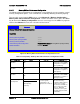
Setup Item
Options
Help Text
Comments
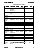
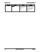
DIMM_A1
DIMM_A2
DIMM_B1
DIMM_B2
DIMM_C1
DIMM_C2
DIMM_D1
DIMM_D2
DIMM_E1
DIMM_E2
DIMM_F1
DIMM_F2
DIMM_G1
DIMM_G2
DIMM_H1
DIMM_H2
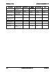
<DIMM Size> <DIMM Status>
Where
DIMM Size: Size of DIMM in
GB
DIMM Status:
Installed&Operational, Not
Installed, Failed/Disabled
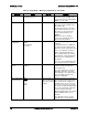
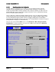
Information only. Displays the status
of each DIMM socket present on the
board. There is one line for each
DIMM socket present on the board.
For each DIMM socket, the DIMM
Status reflects one of the following
three possible states:
Installed&Operational – There is a
DDR3 DIMM installed and
operational in this slot.
Not Installed – There is no DDR3
DIMM installed in this slot.
Failed/Disabled – The DIMM
installed in this slot has failed during
initialization and/or was disabled
during initialization.
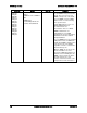
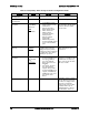
For each DIMM that is in the Installed
& Operational state, the DIMM Size
in GB of that DIMM is displayed. This
is the physical size of the DIMM,
regardless of how it is counted in the
Effective Memory size.
Note: In “DIMM_XY”, X denotes the
Channel Identifier A–P, and Y
denotes the DIMM Slot identifier 1–3
within the Channel. DIMM_A2 is the
DIMM socket on Channel A, Slot 2.
Not all boards have the same
number of channels and slots – this
is dependent on the board features.
Intel order number G44057-007 Revision 1.6
92