
Technical Product Specification


Intel
®
Server System H2000WP Family TPS Hard Disk Drive Support
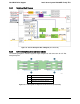
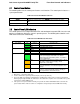
6.3.5 Backplane LED Support
The backplanes support both HDD online and activity/fault LEDs for each of the hard drive
connectors. A light duct in HDD tray is used to conduct LED light to front panel. General HDD
LED functionality is displayed below:
Figure 40. Hard Drive Carrier LED
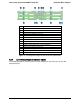
The following tables list the LED functionality:
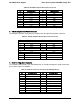
Table 52. Hard Drive Carrier Status LED Functions
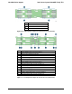
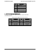
Table 53. Hard Drive Carrier Activity LED Functions
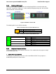
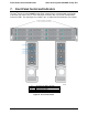
6.3.6 Backplane Connector Definition
The backplanes include several different connectors. This section defines the purpose and pin
out associated with each.
1. 2x9 Pin Power Input Connector
The backplane is powered by +12V and +12V
STB
from PDB of CRPS. The input power is
distributed by backplane to all four nodes.
Amber
Off
No access and no fault
Solid On
Hard Drive Fault has occurred
Blink
Raid rebuild in progress (1hz) Identify (2hz)
Green
Condition
Drive Type
Behavior
Power on with no drive activity.
SAS
LED stays on
SATA
LED stays off
Power on with drive activity.
SAS
LED blinks off when processing a command
SATA
LED blinks off when processing a command
Power on and drive spun down.
SAS
LED stays off
SATA
LED stays off
Power on and drive spinning up.
SAS
LED blinks
SATA
LED stays off
Revision 1.6 Intel order number: G52418-006 61