
Technical Product Specification


Hard Disk Drive Support Intel
®
Server System H2000WP Family TPS
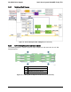
6.3.2 Backplane Block Diagram
Figure 35. Passive Backplane Block Diagram (for one node)
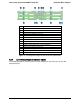
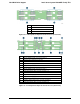
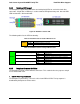
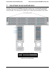
6.3.3 3.5” Hot Swap Backplane Connector scheme
The following diagrams show the layout of major components and connectors for 3.5" Hot
Swap backplane.
A
SATA/SAS connectors for Node 1
B
SATA/SAS connectors for Node 2
C
SATA/SAS connectors for Node 3
D
SATA/SAS connectors for Node 4
Figure 36. 3.5" Backplane Component and Connectors (Front View)
Intel order number: G52418-006 Revision 1.6
58