
Technical Product Specification


Intel
®
Server System H2000WP Family TPS System Boards in the Node Tray
Pin
Signal Name
Pin
Signal Name
Pin
Signal Name
Pin
Signal Name
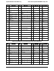
A6
SAS3_TX_P
B6
SAS3_RX_N
A15
GND
B15
SAS0_TX_P
A7
GND
B7
GND
A16
SAS0_RX_N
B16
SAS0_TX_N
A8
GND
B8
GND
A17
SAS0_RX_P
B17
GND
A9
SAS2_RX_N
B9
SAS2_TX_P
A18
GND
B18
NC
The pin definitions for the SATA DOM and Auxiliary Power connectors are the same as defined
in Table 43 and Table 45.
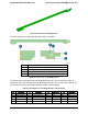
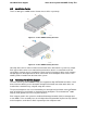
5.4.2 Riser Card
The riser card provides electrical connectivity for installing a standard PCIe x8 Gen3 low profile
form factor adapter card. It supports a PCIe Gen3 x8 card edge connection for passing an
RGMII interface across to the SAS Module. The riser card is secured with two loose screws to
the compute node sheet metal bracket.
Figure 29. Overview of the Riser Card
The riser card pin-out definition is as follows.
Table 50. Card Edge Pin-out of Riser Card to SAS Controller
Pin
Signal Name
Pin
Signal Name
Pin
Signal Name
Pin
Signal Name
A1
P12V
B1
P3V3_1
A26
P3E_RX_DP<
5>
B26
GND
A2
P12V
B2
P3V3_2
A27
P3E_RX_DN<
5>
B27
GND
A3
P12V
B3
P3V3_3
A28
GND
B28
P3E_TX_C_D
P<5>
A4
P12V
B4
SMB_DAT_P3E_P3V3_A
UX
A29
GND
B29
P3E_TX_C_D
N<5>
A5
SMB_CLK_P3E_P3V3
_AUX
B5
P5V_STBY
A30
P3E_RX_DP<
4>
B30
GND
A6
P3V3_AUX
B6
PD_P3E_PRSNT_N
A31
P3E_RX_DN<
4>
B31
GND
A7
GND
B7
LED_HDD_ACT_N
A32
GND
B32
P3E_TX_C_D
P<4>
A8
RGMII_IBMC_RMM4_T
XD_0
B8
RGMII_IBMC_RMM4_RX
D_3
A33
GND
B33
P3E_TX_C_D
N<4>
Revision 1.6 Intel order number: G52418-006 51