
Technical Product Specification


System Boards in the Node Tray Intel
®
Server System H2000WP Family TPS
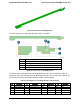
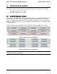
Figure 27. Overview of the Bridge Board
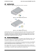
The main connectors on the bridge board are defined as follows.
A
2x40 pin card edge connector (to backplane)
B
SATA DOM Connector
C
Auxiliary SATA DOM Power
D
2x18 pin card edge connector (to SAS Controller)
E
2x40 pin card edge connector ( to bridge slot on baseboard)
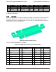
Figure 28. Connectors on the Bridge Board
The pin-out of the card edge to the Hot Swap Backplane is the same as defined in Table 47,
and the pin-out of the card edge to the bridge board slot is the same as defined in Table 46. The
pin-out of the card edge to the SAS controller module is defined below.
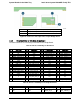
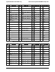
Table 49. Card Edge Pin-out of Bridge Board to SAS Controller
Pin
Signal Name
Pin
Signal Name
Pin
Signal Name
Pin
Signal Name
A1
NC
B1
GND
A10
SAS2_RX_P
B10
SAS2_TX_N
A2
SGPIO_LOAD
B2
SGPIO_DATA_IN
A11
GND
B11
GND
A3
SGPIO_CLOCK
B3
SGPIO_DATA_OUT
A12
SAS1_TX_N
B12
SAS1_RX_P
A4
GND
B4
GND
A13
SAS1_TX_P
B13
SAS1_RX_N
A5
SAS3_TX_N
B5
SAS3_RX_P
A14
GND
B14
GND
Intel order number: G52418-006 Revision 1.6
50