
Technical Product Specification


System Boards in the Node Tray Intel
®
Server System H2000WP Family TPS
A
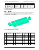
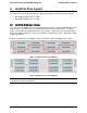
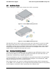
2x40 pin card edge connector (to backplane)
B
2x40 pin card edge connector (to baseboard bridge slot)
C
4-port Mini SAS Connector
Figure 26. Connectors and components on Spare Bridge Board
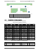
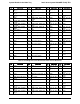
5.3.2 Pinout definition on SAS 6Gbs Bridge Board
The table below lists the connector pin definition on the Bridge Board.
Table 46. Pinout of Card Edge to BaseBoard
Pin
Signal Name
Pin
Signal Name
Pin
Signal Name
Pin
Signal Name
1
5V_AUX
2
5V_AUX
41
PMBUS_ALERT_N
42
SPA_SIN
3
N/C
4
USB2_OC
43
NODE_ON_N
44
IBMC_NODEID_3
5
N/C
6
GND
45
SGPIO_DATA_IN
46
IBMC_NODEID_2
7
GND
8
N/C
47
SGPIO_DATA_OUT
48
IBMC_NODEID_1
9
NODE_PRESENT_N
10
N/C
49
SGPIO_LOAD
50
IBMC_NODEID_0
11
ALL_NODE_OFF
12
GND
51
SPEAKER_IN
52
N/C
13
N/C
14
N/C
53
GND
54
GND
15
GND
16
N/C
55
N/C
56
N/C
17
IPMB_DATA
18
GND
57
N/C
58
N/C
19
IPMB_CLK
20
LED_HDD_ACT_N
59
GND
60
GND
21
GND
22
FP_ACT_LED_N
61
N/C
62
N/C
23
SMB_SNSR_DATA
24
FP_LED_STSA_N
63
N/C
64
N/C
25
SMB_SNSR_CLK
26
FP_LED_STSG_N
65
GND
66
GND
27
GND
28
FP_PWR_LED_N
67
N/C
68
N/C
29
SMB_HSBP_DATA
30
FP_ID_LED_N
69
N/C
70
N/C
31
SMB_HSBP_CLK
32
FP_ID_BTN_N
71
GND
72
GND
33
GND
34
FP_RST_BTN_N
73
N/C
74
N/C
35
SMB_PMBUS_DAT
A
36
FP_PWR_BTN_N
75
N/C
76
N/C
37
SMB_PMBUS_CLK
38
FP_NMI_BTN_N
77
GND
78
GND
39
GND
40
SPA_SOUT
79
GND
80
SAS_SATA_SET_N
Table 47. Pinout of Card Edge to Hot Swap Back Plane
Pin
Signal Name
Pin
Signal Name
Pin
Signal Name
Pin
Signal Name
1
5V_AUX
2
5V_AUX
41
PMBUS_ALERT_N
42
SPA_SIN
3
N/C
4
N/C
43
NODE_ON_N
44
IBMC_NODEID_3
5
N/C
6
GND
45
SGPIO_DATA_IN
46
IBMC_NODEID_2
Intel order number: G52418-006 Revision 1.6
48