
Technical Product Specification


System Boards in the Node Tray Intel
®
Server System H2000WP Family TPS
5V_AUX power generated on HSBP and provided to the compute node.
3.3V power generated on HSBP and provided to bridge board to run SAS/SATA re-
drivers.
Global PMBus* alert signal for CLST support.
Four SMB bus interfaces:
o SMBUS* R1 - For chassis temp sensor and chassis FRU EEPROM device.
o SMBUS* R5 - Connectivity for up to two HSBP controllers and one shared 12V
current monitoring device.
o SMBUS* R7 - Connectivity for up to two common redundant power supply (CRPS)
module PMBus*.
o IPMB - For OEM requirement not used on EPSD HW servers.
o Front panel button signals: Power, reset, NMI, and ID.
o Front panel LEDs signals: Power, fault, status, fabric activity, ID, HDD activity.
One 7-pin 6Gb SATA port connector for DOM device docking to the bridge board.
USB2.0 interface to a 4-pin type-A connector for flash device docking to bridge board.
2-Pin 5V_AUX power for the SATA DOM in need of cabling power.
Power connector for SATA DOM.
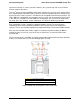
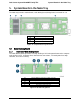
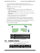
A
2x40 pin card edge connector (to backplane)
B
USB 2.0 Type-A connector
C
2-pin 5V_AUX power
D
AHCI SATA0 DOM port connector
E
2x40 pin card edge connector (to baseboard slot)
Figure 24. Connectors on Bridge Board
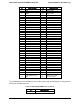
5.2.2 Pinout definition on Bridge Board
The table below lists the connector type and pin definition for a Bridge Board.
Table 42. Card Edge Connector Pinout
Pin
Signal Description
Pin
Signal Description
1
5V Aux
2
5V Aux
3
SATA0_TXN
4
USB2_OC
Intel order number: G52418-006 Revision 1.6
44