
Technical Product Specification


Intel
®
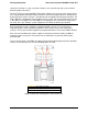
Server System H2000WP Family TPS System Boards in the Node Tray
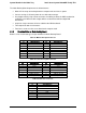
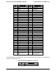
Table 41. Main Power Output Connector
Pin
Signal Description
Pin
Signal Description
1
GND
7
P12V_HS
2
GND
8
P12V_HS
3
GND
9
P12V_HS
4
GND
10
P12V_HS
5
GND
11
P12V_HS
6
GND
12
P12V_HS
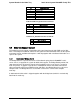
5.2 Bridge Board
5.2.1 Overview of Bridge Board
The Bridge Board provides hot swap interconnect of all electrical signals to the backplane of the
server chassis (except for main 12V power). It supports up to 4x lanes of SAS/SATA, a 7-pin
SATA connector for SATA DOM devices, and type-A USB connector for USB flash device. One
Bridge Board is used per one compute node. The Bridge Board is secured with three loose
screws to the compute node tray.
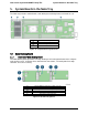
Figure 23. Bridge Board Overview
Bridge board passes all electrical connectivity through a 2x40pin card edge hot swap
interconnect between compute node and chassis backplane. The bridge board passes the
follow features (per compute node) to the backplane of the server:
4x 6Gb SAS/SATA ports for HSBP drives. (Intel
®
Server Board S2600WP and
S2600WPQ family on board SCU supports 3Gb SAS/SATA while the bridge board and
the HSBP of Intel
®
Server System H2000WP family support 6Gb SAS/SATA drives.)
Two x4 lane 6Gb SAS/SATA re-drivers.
Four chassis ID signals to determine the physical location of the compute node.
One SGPIO SFF-8485 interface to the HSBP microcontroller.
Revision 1.6 Intel order number: G52418-006 43