
Technical Product Specification


System Boards in the Node Tray Intel
®
Server System H2000WP Family TPS
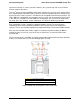
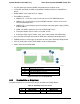
The Node Docking Board implements the below features:
Main 12V hot swap connectivity between compute node and chassis power.
Current sensing of 12V main power for use with node manager.
One 2x6pin mini-fit jr high current connectors for cabling to either the HW baseboard or
a GPGPU card. Different cable lengths will be needed for the different depth HW
baseboards.
2x7pin fan single connector, discrete cabled to the HW baseboard.
Three 8pin dual rotor fan connectors.
Four loose screws used to secure board to the compute node.
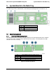
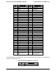
5.1.2 Pinout definition on Node Docking Board
Below is a list of connector type and pin definition on Node Docking Board.
Table 38. Main Power Input Connector
Pin
Signal Description
Pin
Signal Description
Lower Blade (Circuit 1)
1
GND
2
GND
3
GND
4
GND
5
GND
6
GND
Upper Blade (Circuit 2)
7
P12V
8
P12V
9
P12V
10
P12V
11
P12V
12
P12V
Table 39. Fan Control Signal Connector
Pin
Signal Description
Pin
Signal Description
1
PWM1
2
Reserved
3
Tach0
4
Tach1
5
Tach2
6
Tach3
7
Tach4
8
Tach5
9
NODE_ON
10
GND
11
SMBUS_R4 CLK
12
SMBUS_R4 DAT
13
NODE_ADR0
14
NODE_PWRGD
Table 40. Node Fan Connector
Pin
Signal Description
1
GND
2
P12V
3
TACH1
4
PWM1
5
GND
6
P12V
7
TACH2
8
PWM1
Intel order number: G52418-006 Revision 1.6
42