
Technical Product Specification


Intel
®
Server System H2000WP Family TPS Cooling Sub-System
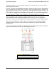
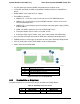
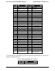
The fan connector pin-out definition is as follows:
Table 37. 8-pin Connector Pin-Out for Node Dual Rotor Fans
Pin
Signal Name
Description
1
GND
Ground
2
P12V
Power Supply +12 V
3
Tach1 Out
FAN_TACH1 signal output
4
PWM1 In
PWM1 signal input
5
GND
Ground
6
P12V
Power Supply +12 V
7
Tach2 Out
FAN_TACH2 signal output
8
PWM1 In
PWM1 signal input
4.3 Power Supply Fan
Each power supply module supports one non-redundant dual rotor 40 mm fan. The fans control
the cooling of the power supply and some drive bays. These fans are not replaceable. Therefore,
if a power supply fan fails, you must replace the power supply module.
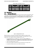
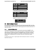
4.4 Air Duct Module
Each node requires the use of an air duct module to direct airflow over critical areas within the
node. Before slide the node tray into chassis, make sure the air duct is installed properly.
Figure 20. Compute Node Air Duct
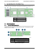
4.5 Drive Bay Population Requirement
In order to maintain system thermal requirements, you must fully populate all hard drive bays.
Hard drive trays used for hot-swap drives must either have a hard drive installed or not have a
hard drive installed.
If only one power supply unit is used, a PSU dummy filler must be used to match the airflow
requirement.
Revision 1.6 Intel order number: G52418-006 39