
Technical Product Specification


Cooling Sub-System Intel
®
Server System H2000WP Family TPS
replace the failed fan as soon as possible. However, the system design still reserves limited
thermal margin to fan failure.
The Intel
®
Server System H2216WP Family which supports up to 16 units of 2.5" storage drives
does support optimal redundant cooling. Certain level of CPU throttling will occur during fan fail
but the percent is below 1% which is considered to be acceptable from thermal perspective. For
TDP 130W CPU configuration, the confidence level of system exit air temperature to meet 70°C
is 98% which is acceptable. For TDP 95W CPU configuration, the system exit air temperature
can meet 70°C spec. All other system components are within the thermal specification.
Each fan within the node is capable of supporting multiple speeds. Fan speed changes
automatically when internal ambient temperature of the system or processor temperature
changes. The fan speed control algorithm is programmed into the server board’s BMC software.
Each fan connector within the module supplies a tachometer signal that allows the BMC to
monitor the status of each fan. If one of the fans should fail, the system fault LED on front
panel will light.
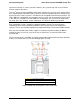
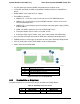
The fan control signal is from BMC on mother board to Node Docking Board and then distribute
to three sets of dual rotor fans. See the following figure for detail.
Yellow Lines: Fan cable connection
Red line: Base board power cable connection
Blue line: Fan control signal cable connection
Figure 19. Node Fan Set and power/control Connection
Intel order number: G52418-006 Revision 1.6
38