
Technical Product Specification


Intel® Server System P4000IP and Intel® Workstation System P4000CR Family TPS System Power Sub-system
66 Intel order number G38159-002 Revision 1.2
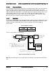
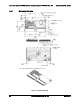
for future 0.093'' PCBs in the system. The card edge connector has no keying features; the
keying method is accomplished by the system sheet metal.
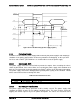
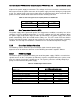
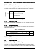
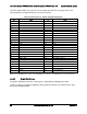
Table 68. Input Connector and Pin Assignment Diagrams
Pin
Name
Pin
Name
A1
GND
B1
GND
A2
GND
B2
GND
A3
GND
B3
GND
A4
GND
B4
GND
A5
GND
B5
GND
A6
GND
B6
GND
A7
GND
B7
GND
A8
GND
B8
GND
A9
GND
B9
GND
A10
+12V
B10
+12V
A11
+12V
B11
+12V
A12
+12V
B12
+12V
A13
+12V
B13
+12V
A14
+12V
B14
+12V
A15
+12V
B15
+12V
A16
+12V
B16
+12V
A17
+12V
B17
+12V
A18
+12V
B18
+12V
A19
PMBus SDA
B19
A0 (SMBus address)
A20
PMBus SCL
B20
A1 (SMBus address)
A21
PSON
B21
12V stby
A22
SMBAlert#
B22
Cold Redundancy Bus
A23
Return Sense
B23
12V load share
A24
+12V remote Sense
B24
No Connect
A25
PWOK
B25
Compatibility Pin
*
Note: *The compatibility Pin is used for soft compatibility check. The two compatibility pins are connected directly.
2.4.2.2 Output Wire Harness
The power distribution board has a wire harness output with the following connectors.
Listed or recognized component appliance wiring material (AVLV2), CN, rated min 85
C shall
be used for all output wiring.