
Quick Installation Guide Part 2


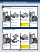
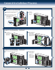
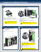
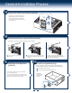
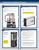
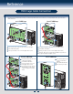
Table Of Contents
13
General Installation Process
A
14
Install Second Power Supply Module (optional)
Latch
Handle
Finger
Hole
A
B
A
B
Use the 'finger hole' to remove the
filler panel.
Insert the power supply module into the power
supply cage and push all the way until it clicks
into place.
To remove a power supply module, push the
green latch in the direction shown while pulling
out of the system by the handle.
Note: Applies only to the chassis with hot-swap power supply configuration.
16
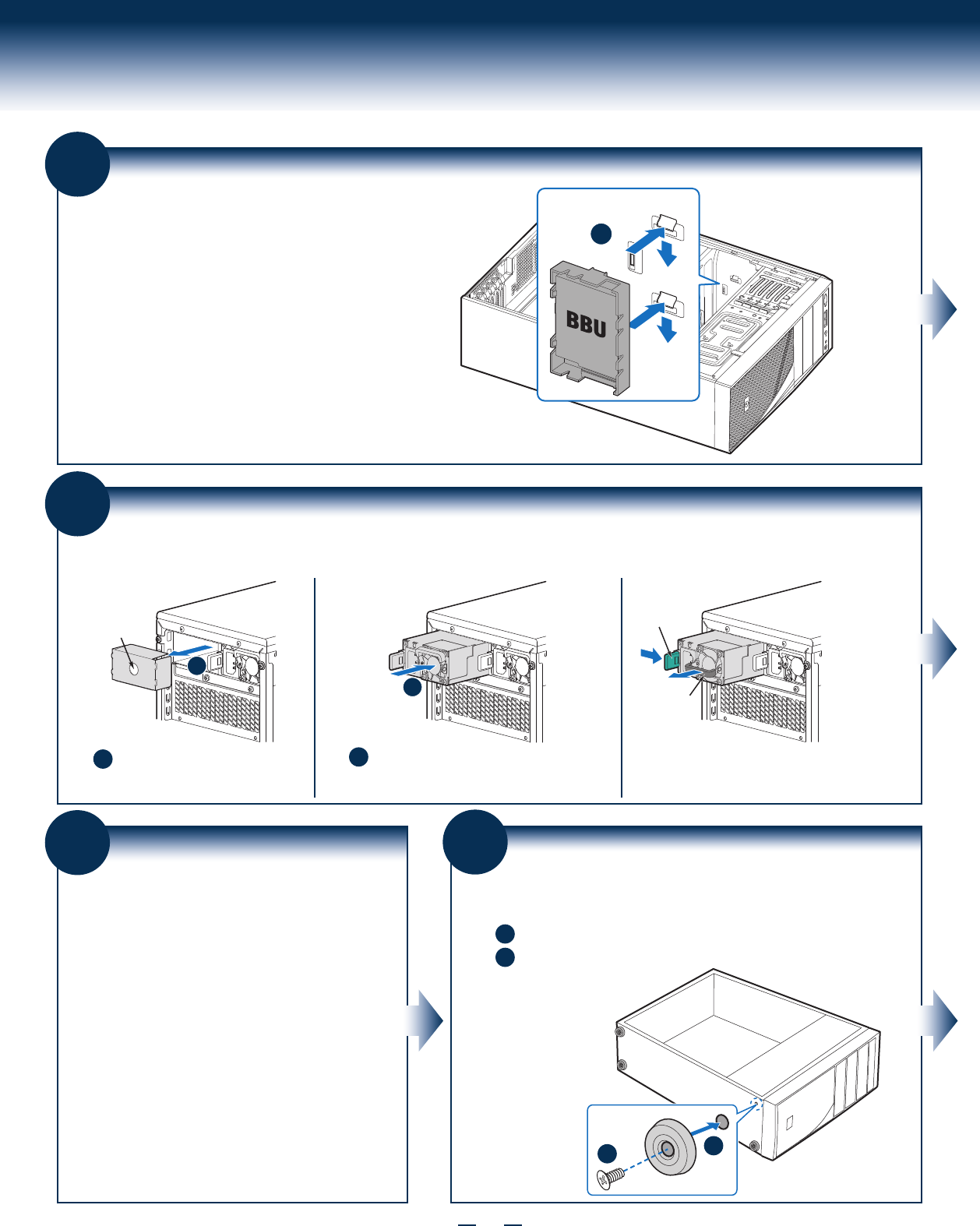
Install Feet (pedestal only)
Insert rubber foot into chassis hole.
A
Secure foot by inserting pin through the rubber foot.
B
A
B
Note: This step applies to your chassis if configured as a pedestal system. If
you plan to configure your chassis as a rack-mount system, disregard this step.
Note: Repeat
above steps until
all four feet are
installed.
13
Install Intel® RAID Smart Battery (optional)
Align the tabs on the plastic battery holder
with the mounting holes in the chassis and
slide the plastic battery holder toward the
front of the chassis until the tabs engage with
the mounting holes.
A
15
Rack Mount Configuration
(optional)
If you intend to configure your server as a pedestal
system, disregard this step.
If you intend to configure your server as a rack mount
system, go to the instructions that came with your Rack
Mount Kit to complete your server assembly.
•
•