
Quick Installation Guide Part 2


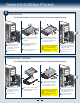
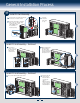
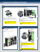
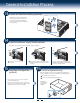
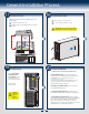
Table Of Contents
16
Reference
Front Panel Controls and Indicators
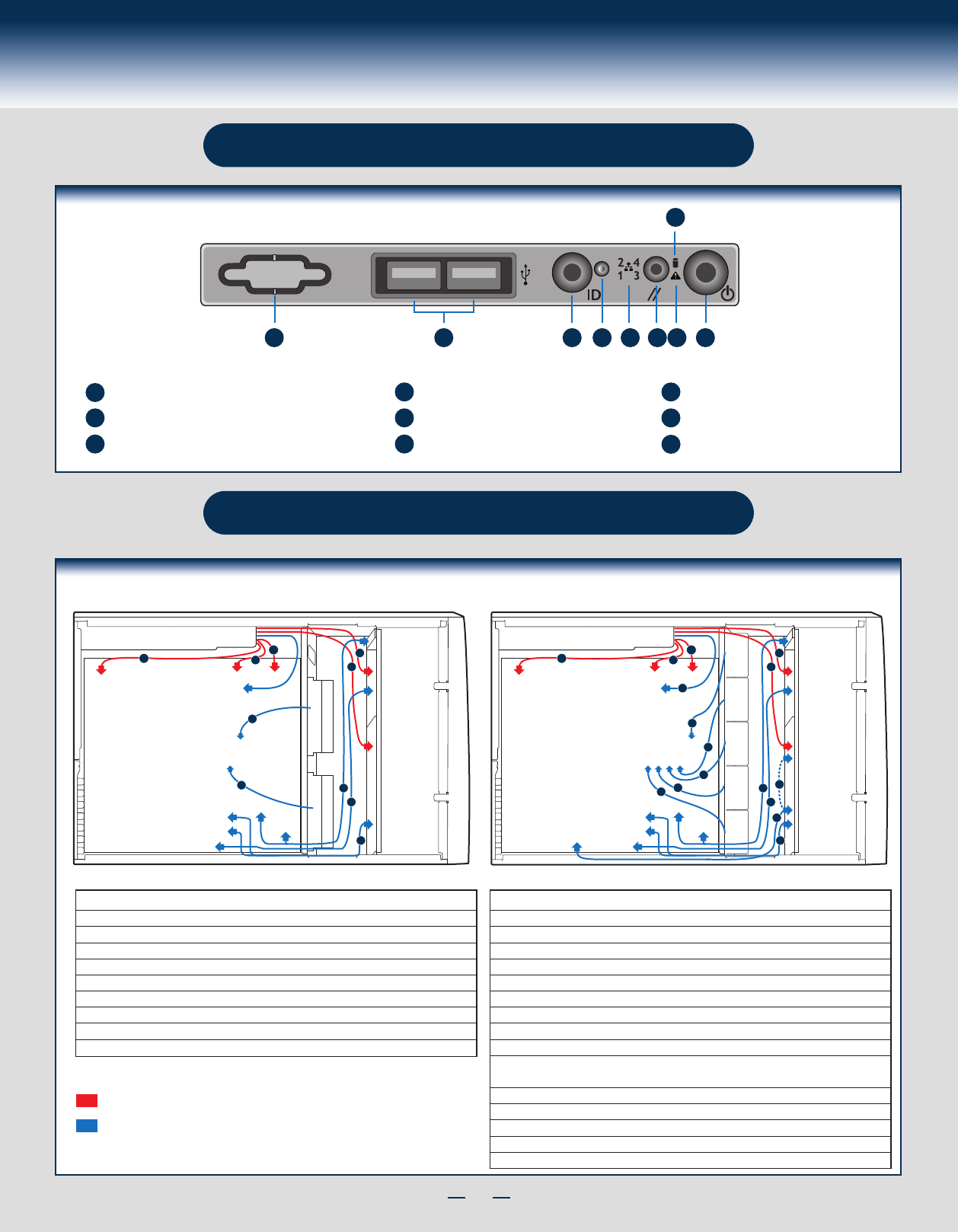
Cable Routing Diagram
A
B C
D
E F
G
H
I
A
B
C
D
E
F
G
H
I
ID Button with ID LED Integrated
USB Connectors
Reservation(Optional VGA/Serial Port)
System Reset Button
NIC LED System Power Button with Power LED
HDD Activity LED
System Status LEDNMI Button
RED indicates power cable routing
BLUE indicates data cable routing
Figure 1 Figure 2
A. CPU1/CPU2 Power Cable
B. Server Board Main Power Cable
C. Fixed HDD Power Cable
D. ODD Power Cable
E. Front Panel Cable, USB Cable
F. ODD Data Cable (Connect To White SATA 6G Connectors On Server Board)
G. Fixed HDD Data Cable
H. System FAN 1
I. System FAN 2
Description
A. CPU1/CPU2 Power Cable
B. Server Board Main Power Cable
C. Backplane Power Cable
D. ODD Power Cable
E. Front Panel Cable, USB Cable
F. ODD Data Cable (Connect To White SATA 6G Connectors On Server Board)
G. MiniSAS (with SGPIO) Cable
H. PMBus Cable
I. HSBP_I
2
C Cable (From Server Board To First Backplane)
J. HSBP_I
2
C Cable (From First Backplane To Second Backplane when Second
Backplane Available)
K. System FAN 1
L. System FAN 2
M. System FAN 3
N. System FAN 4
O. System FAN 5
Description
FAN_3
FAN_2
FAN_1
FAN_4
FAN_5
Server Board
Power Supply
CPU2
CPU1
Main Power
Front
Panel
SAS/SATA
ODD
SAS/SATA
HSBP_I
2
C
USB
PMBus
B
A
A
D
C
I
J
G
E
F
K
L
N
M
O
H
FAN_2
FAN_1
Server Board
Power Supply
CPU2
Main Power
Front
Panel
SAS/SATA
ODD
SAS/SATA
USB
PMBus
CPU1
B
A
A
D
C
G
E
F
H
I