
Technical Product Specification


Front Control Panel and I/O Panel Overview Intel
®
Server System R1000EP Product Family TPS
44 Intel Order Number G67599-003 Revision 2.0
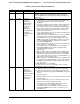
Color
State
Criticality
Description
Amber
Solid on
Critical, non-
recoverable –
System is halted
Fatal alarm – system has failed or shutdown:
1. CPU CATERR signal asserted
2. MSID mismatch detected (CATERR also asserts for this case).
3. CPU 1 is missing
4. CPU Thermal Trip
5. No power good – power fault
6. DIMM failure when there is only 1 DIMM present and hence no
good memory present
1
.
7. Runtime memory uncorrectable error in non-redundant mode.
8. DIMM Thermal Trip or equivalent
9. SSB Thermal Trip or equivalent
10. CPU ERR2 signal asserted
11. BMC\Video memory test failed. (Chassis ID shows blue/solid-on
for this condition)
12. Both uBoot BMC FW images are bad. (Chassis ID shows
blue/solid-on for this condition)
13. 240VA fault
14. Fatal Error in processor initialization:
a. Processor family not identical
b. Processor model not identical
c. Processor core/thread counts not identical
d. Processor cache size not identical
e. Unable to synchronize processor frequency
f. Unable to synchronize QPI link frequency
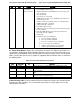
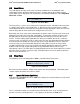
G – Power/Sleep Button: Toggles the system power on and off. This button also functions as a
sleep button if enabled by an ACPI compliant operating system. Pressing this button will send a
signal to the Integrated BMC, which will either power on or power off the system. The integrated
LED is a single color (Green) and is capable of supporting different indicator states as defined in
the following table:
Table 20. Power/Sleep LED Functional States
State
Power Mode
LED
Description
Power-off
Non-ACPI
Off
System power is off, and the BIOS has not initialized the chipset.
Power-on
Non-ACPI
On
System power is on
S5
ACPI
Off
Mechanical is off, and the operating system has not saved any context
to the hard disk.
S4
ACPI
Off
Mechanical is off. The operating system has saved context to the hard
disk.
S3-S1
ACPI
Slow blink
DC power is still on. The operating system has saved context and
gone into a level of low-power state.
S0
ACPI
Steady on
System and the operating system are up and running.
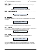
H- Drive Activity LED: The drive activity LED on the front panel indicates drive activity from the
on-board hard disk controllers. The server board also provides a header giving access to this
LED for add-in controllers.