
Technical Product Specification


Thermal Management Intel
®
Server System R1000EP Product Family TPS
24 Intel Order Number G67599-003 Revision 2.0
Selecting an altitude range that is lower than the actual altitude the system will be operating at,
can cause the fan control system to operate less efficiently, leading to higher system thermals
and lower system performance. If the altitude range selected is higher than the actual altitude
the system will be operating at, the fan control system may provide better cooling but with
higher acoustics and higher fan power consumption. If the altitude is not known, selecting a
higher altitude is recommended in order to provide sufficient cooling
4.2.3 Set Fan Profile
This option is used to set the desired Fan Profile. Available settings include:
[Performance] and [Acoustic].
The Acoustic mode offers best acoustic experience and appropriate cooling capability covering
mainstream and majority of the add-in cards with 100LFM thermal requirements. Performance
mode is designed to provide sufficient cooling capability covering all kinds of add-in cards on the
market. For any add-in card requiring more than 100LFM, performance mode must be selected
to provide sufficient cooling capability.
4.2.4 Fan PWM Offset
This option is reserved for manual adjustment to the minimum fan speed curves. The valid
range is from [0 to 100] which stands for 0% to 100% PWM adding to the minimum fan speed.
This feature is valid when Quiet Fan Idle Mode is at Enabled state. The default setting is [0].
4.2.5 Quiet Fan Idle Mode
This feature can be [Enabled] or [Disabled]. If enabled, the fans will either shift to a lower speed
or stop when the aggregate sensor temperatures are satisfied, indicating the system is at ideal
thermal/light loading conditions. When the aggregate sensor temperatures are not satisfied, the
fans will shift back to normal control curves. If disabled, the fans will never shift into lower fan
speeds or stop, regardless of whether the aggregate sensor temperatures are satisfied or not.
The default setting is [Disabled].
Note: The above feature may or may not be in effect and depends on the actual thermal
characteristics of the specified system.
4.2.6 Thermal Sensor Input for Fan Speed Control
The BMC uses various IPMI sensors as inputs to fan speed control. Some of the sensors are
actual physical sensors and some are “virtual” sensors derived from calculations.
The following IPMI thermal sensors are used as input to fan speed control:
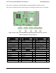
Front Panel Temperature Sensor
1
CPU Margin Sensors
2,4,5
DIMM Thermal Margin Sensors
2,4
Exit Air Temperature Sensor
1,7, 9
PCH Temperature Sensor
3,5
On-board Ethernet Controller Temperature Sensors
3, 5
Add-In Intel
®
SAS/IO Module Temperature Sensors
3, 5
PSU Thermal Sensor
3, 8
CPU VR Temperature Sensors
3, 6