
Technical Product Specification


Platform Management Functional Overview Intel
®
Server Board S2400EP TPS
Intel order number G50763-002 Revision 2.0
78
Display of processor and memory information as is available over IPMI over LAN.
Ability to get and set Node Manager (NM) power policies.
Display of power consumed by the server.
Ability to view and configure VLAN settings.
Warn user the reconfiguration of IP address will cause disconnect.
Capability to block logins for a period of time after several consecutive failed login
attempts. The lock-out period and the number of failed logins that initiates the lock-out
period are configurable by the user.
Server Power Control - Ability to force into Setup on a reset.
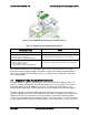
6.9.14 Virtual Front Panel
Virtual Front Panel is the module present as “Virtual Front Panel” on the left side in the
embedded web server when "remote Control" tab is clicked.
Main Purpose of the Virtual Front Panel is to provide the front panel functionality virtually.
Virutal Front Panel (VFP) will mimic the status LED and Power LED status and Chassis ID
alone. It is automatically in sync with BMC every 40 seconds.
For any abnormal status LED state, Virtual Front Panel will get the reason behind the
abnormal or status LED changes and displayed in VFP side.
As Virtual Front Panel uses the chassis control command for power actions. It won’t log
the Front button press event since Logging the front panel press event for Virtual Front
Panel press will mislead the administrator.
For Reset via Virtual Front Panel, the reset will be done by a “Chassis control” command.
For Reset via Virtual Front Panel, the restart cause will be because of “Chassis control”
command.
During Power action, Power button/Reset button should not accept the next action until
current Power action is complete and the acknowledgment from BMC is received.
EWS will provide a valid message during Power action until it completes the current Power
action.
The VFP does not have any effect on whether the front panel is locked by “Set Front
Panel Enables” command.
The chassis ID LED provides a visual indication of a system being serviced. The state of
the chassis ID LED is affected by the following actions:
Toggled by turning the chassis ID button on or off.
There is no precedence or lock-out mechanism for the control sources. When a new
request arrives, previous requests are terminated. For example, if the chassis ID button is
pressed, then the chassis ID LED changes to solid on. If the button is pressed again, then
the chassis ID LED turns off.