
Technical Product Specification


Intel
®
Server Board S2400EP TPS Product Architecture Overview
Revision 2.0 Intel order number G50763-002
37
3.3.4 Network Interface
On-board network connectivity is provided by means of two onboard Intel
®
Ethernet Controller
I350 providing up to two 10/100/1000 Mb Ethernet ports. The NIC chip is supported by
implementing x4 PCIe Gen2 signals from the Intel
®
C600 PCH.
On the Intel
®
Server Board S2400EP2, two external 10/100/1000 Mb RJ45 Ethernet ports are
provided. On the Intel
®
Server Board S2400EP4, four external 10/100/1000 Mb RJ45 Ethernet
ports are provided.
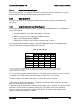
Each Ethernet port drives two LEDs located on each network interface connector. The LED at
the right of the connector is the link/activity LED and indicates network connection when on,
and transmit/receive activity when blinking. The LED at the left of the connector indicates link
speed as defined in the following table.
Table 8. External RJ45 NIC Port LED Definition
LED Color
LED State
NIC State
Green/Amber (Right)
Off
10 Mbps
Amber
100 Mbps
Green
1000 Mbps
Green (Left)
On
Active Connection
Blinking
Transmit/Receive activity
The server board has seven MAC addresses programmed at the factory for S2400EP4. MAC
addresses are assigned as follows:
NIC 1 MAC address (for OS usage)
NIC 2 MAC address = NIC 1 MAC address + 1 (for OS usage)
NIC 3 MAC address = NIC 1 MAC address + 2 (for OS usage)
NIC 4 MAC address = NIC 1 MAC address + 3 (for OS usage)
BMC LAN channel 1 MAC address = NIC1 MAC address + 4
BMC LAN channel 2 MAC address = NIC1 MAC address + 5
BMC LAN channel 3 (RMM4) MAC address = NIC1 MAC address + 6
The server board has five MAC addresses programmed at the factory for S2400EP2. MAC
addresses are assigned as follows:
NIC 1 MAC address (for OS usage)
NIC 2 MAC address = NIC 1 MAC address + 1 (for OS usage)