
Technical Product Specification


Intel
®
Light Guided Diagnostics Intel
®
Server Board S2400EP TPS
Intel order number G50763-002 Revision 2.0
110
A BMC FW update, upon receiving a BMC cold reset command
Upon a BMC watchdog initiated reset.
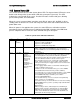
The following table defines the LED states during the BMC Boot/Reset process:
Table 53. BMC Boot/Reset Status LED Indicators
BMC Boot/Reset State
Chassis ID LED
Status LED
Comment
BMC/Video memory test failed
Solid Blue
Solid Amber
Nonrecoverable condition.
Contact your Intel
®
representative for information on
replacing this motherboard.
Both Universal Bootloader (u-Boot)
images bad
Solid Blue
Solid Amber
Non-recoverable condition.
Contact your Intel
®
representative for information on
replacing this motherboard.
BMC in u-Boot
Blink Blue
3Hz
Blink Green
1Hz
Blinking green indicates
degraded state (no
manageability), blinking blue
indicates u-Boot is running but
has not transferred control to
BMC Linux*. Server will be in this
state 6-8 seconds after BMC
reset while it pulls the Linux*
image into flash.
BMC Booting Linux*
Solid Blue
Solid Green
Solid green with solid blue after
an AC cycle/BMC reset,
indicates that the control has
been passed from u-Boot to
BMC Linux* itself. It will be in this
state for ~10-~20 seconds.
End of BMC boot/reset process.
Normal system operation
Off
Solid Green
Indicates BMC Linux* has
booted and manageability
functionality is up and running.
Fault/Status LEDs operate as
per usual.
10.4 Post Code Diagnostic LEDs
A bank of eight POST code diagnostic LEDs are located on the back edge of the server next to
the stacked USB connectors. During the system boot process, the BIOS executes a number of
platform configuration processes, each of which is assigned a specific hex POST code number.
As each configuration routine is started, the BIOS displays the given POST code to the POST
code diagnostic LEDs. The purpose of these LEDs is to assist in troubleshooting a system hang
condition during the POST process. The diagnostic LEDs can be used to identify the last POST
process to be executed. See Appendix D for a complete description of how these LEDs are
read, and for a list of all supported POST codes
10.5 5 Volt Stand-By Present LED
This LED is illuminated when a power cord (AC or DC) is connected to the server and the
power supply is supplying 5 Volt Stand-by power to the server board. This LED is intended as a
service caution indicator to anyone accessing the inside of the server system.