
Technical Product Specification


Intel
®
Server Board S2400EP TPS Jumper Blocks
Revision 2.0 Intel order number G50763-002
103
7. The STARTUP.NSH file automatically executes and initiates the flash update. When
complete, the IFlash utility will display a message.
8. Power OFF the system and return the BIOS Recovery jumper to its default position.
9. Power ON the system.
10. Do NOT interrupt the BIOS POST during the first boot.
11. Configure desired BIOS settings.
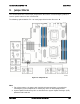
9.2 Management Engine (ME) Firmware Force Update Jumper Block
When the ME Firmware Force Update jumper is moved from its default position, the ME is
forced to operate in a reduced minimal operating capacity. This jumper should only be used if
the ME firmware has gotten corrupted and requires re-installation. The following procedure
should be followed.
Note: System Update and Recovery files are included in the System Update Packages (SUP)
posted to Intel’s web site.
1. Turn off the system and remove power cords.
2. Remove Riser Card Assembly #2.
3. Move the ME FRC UPD Jumper from the default (pins 1 and 2) operating position to the
Force Update position (pins 2 and 3).
4. Re-attach system power cords.
5. Power on the system.
Note: System Fans will boost and the BIOS Error Manager should report an 83A0 error code
(ME in recovery mode).
6. Boot to the EFI shell and update the ME firmware using the “MEComplete####.cap” file
(where #### = ME revision number) using the following command: iflash32 /u /ni
MEComplete####.cap.
7. When update has successfully completed, power off system.
8. Remove AC power cords.
9. Move ME FRC UPD jumper back to the default position.
Note: If the ME FRC UPD jumper is moved with AC power applied, the ME will not operate
properly. The system will need have the AC power cords removed, wait for at least 10 seconds
and then reinstalled to ensure proper operation.
10. Install PCI Riser.
11. Install AC power cords .
12. Power on system.