
Technical Product Specification


On-board Connector/Header Overview Intel
®
Server Board S2400EP TPS
Intel order number G50763-002 Revision 2.0
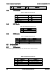
100
Pin
Signal Name
Description
1
USB_PWR_5V
USB power
2
USB_PWR_5V
USB power
3
USB _PN_CONN
USB port negative signal
4
USB _PN_CONN
USB port negative signal
5
USB _PP_CONN
USB port positive signal
6
USB _PP_CONN
USB port positive signal
7
Ground
8
Ground
9
Key
No pin
10
TP_USB _NC
Test point
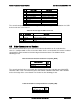
The server board provides one additional Type A USB port to support the installation of a USB
device inside the server chassis.
Table 48. Internal Type A USB Port Pin-out
Pin
Signal Name
Description
1
USB_PWR7_5
V
USB_PWR
2
USB_PN
USB port negative signal
3
USB _PP
USB port positive signal
4
GND
Ground
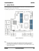
8.8 Other Connectors and Headers
The server board includes a 2-pin chassis intrusion header which can be used when the
chassis is configured with a chassis intrusion switch. On the server board, this header is labeled
“CHAS INTR” and is located on the front edge of the server board. The header has the
following pin-out.
Table 49. Chassis Intrusion Header Pin-out (CHAS_INTR)
Signal Description
Pin
#
FP_CHASSIS_INTRUSION
1
GROUND
2
The server board includes a 2-pin hard drive activity LED header used with some SAS/SATA
controller add-in cards. On the server board, this header is labeled “HDD LED” and is located
on the front edge of the server board. The header has the following pin-out.
Table 50. Hard Drive Activity Header Pin-out (HDD_LED)
Signal Description
Pin
#
LED_HDD_ACT_N
1
TP_LED_HDD_ACT
2