
Technical Product Specification


Intel
®
Server Board S2400EP TPS On-board Connector/Header Overview
Revision 2.0 Intel order number G50763-002
99
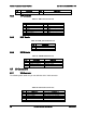
Pin
Signal Name
Description
7
GND
Ground
8
GND
Ground
9
P5V
+5V DC
10
GND
Ground
11
TP_VID_CONN_B11
No connection
12
V_IO_DDCDAT
DDCDAT
13
V_IO_HSYNC_CONN
HSYNC (horizontal sync)
14
V_IO_VSYNC_CONN
VSYNC (vertical sync)
15
V_IO_DDCCLK
DDCCLK
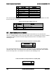
8.7.2 NIC Connectors
The server board provides two stacked RJ-45/2xUSB connectors side-by-side on the back edge
of the board. The pin-out for NIC connectors is identical and defined in the following table.
Table 45. RJ-45 10/100/1000 NIC Connector Pin-out
Pin
Signal Name
1
GND
2
P1V8_NIC
3
NIC_A_MDI3P
4
NIC_A_MDI3N
5
NIC_A_MDI2P
6
NIC_A_MDI2N
7
NIC_A_MDI1P
8
NIC_A_MDI1N
9
NIC_A_MDI0P
10
NIC_A_MDI0N
11
NIC_LINKA_1000_N (LED
12
NIC_LINKA_100_N (LED)
13
NIC_ACT_LED_N
14
NIC_LINK_LED_N
15
GND
16
GND
8.7.3 USB Connector
The following table details the pin-out of the external USB connectors found on the back edge
of the server boards.
Table 46. External USB Connector Pin-out
Pin
Signal Name
Description
1
USB_OC_5VSB
USB_PWR
2
USB_PN
DATAL0 (Differential data line paired with DATAH0)
3
USB_PP
DATAH0 (Differential data line paired with DATAL0)
4
GND
Ground
One 2x5 connectors on the server board provide support for four additional USB ports.
Table 47. Internal USB Connector Pin-out
Pin
Signal Name
Description