
Technical Product Specification


Intel
®
Server Board S2400EP TPS On-board Connector/Header Overview
Revision 2.0 Intel order number G50763-002
95
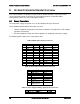
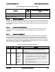
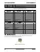
Signal Description
Pin#
Pin#
Signal Description
GROUND
A12
B12
GROUND
SAS6_RX_C_DP
A13
B13
SAS6_TX_C_DP
SAS6_RX_C_DN
A14
B14
SAS6_TX_C_DN
GROUND
A15
B15
GROUND
SAS7_RX_C_DP
A16
B16
SAS7_TX_C_DP
SAS7_RX_C_DN
A17
B17
SAS7_TX_C_DN
GROUND
A18
B18
GROUND
GROUND
MTH1
MTH5
GROUND
GROUND
MTH2
MTH6
GROUND
GROUND
MTH3
MTH7
GROUND
GROUND
MTH4
MTH8
GROUND
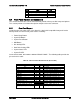
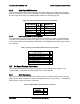
8.3.3 Internal Type-A USB Connector
The server board includes one internal Type-A USB connector labeled “USB_6” and is located
near the back edge of the board next to the Riser 1 slot. The following table provides the pin-
out for this connector.
Table 35. Internal Type-A USB Connector Pin-out (USB_6)
Signal Description
Pin
#
P5V_USB_INT
1
USB2_P2_F_D
N
2
USB2_P2_F_DP
3
GROUND
4
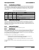
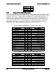
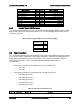
8.4 Fan Connectors
The server board provides three SSI-compliant 4-pin and five SSI-compliant 10-pin fan headers
to use as CPU and I/O cooling fans. Each 10-pin connector is monitored and controlled by on-
board platform management. On the server board, each system fan connector is labeled
“SYS_FAN #”, where # = 1 thru 5. The following table provides the pin-out for all
fan connectors.
Two 4-pin fan headers are designated as processor cooling fans:
o CPU1 fan
o CPU2 fan
Four 10-pin fan headers are designated as hot-swap system fans:
o Hot-swap system fan 1
o Hot-swap system fan 2
o Hot-swap system fan 3
o Hot-swap system fan 4
o Hot-swap system fan 5
Table 36. SSI 4-pin Fan Header Pin-out
Pin
Signal Name
Type
Description