
Technical Product Specification


Intel
®
Server Board S2400EP TPS On-board Connector/Header Overview
Revision 2.0 Intel order number G50763-002
89
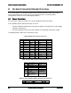
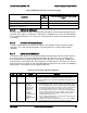
Pin
Signal
Color
2
SMB_DAT_FP_PWR_R
Black
3
SMB_ALRT_3_ESB_R
Red
4
3.3 V SENSE-
Yellow
5
3.3 V SENSE+
Green
8.2 Front Panel Headers and Connectors
The server board includes several connectors that provide various possible front panel options.
This section provides a functional description and pin-out for each connector.
8.2.1 Front Panel Support
Included on the front edge of the server board is a 30-pin SSI compatible front panel header
which provides for various front panel features including:
Power/Sleep Button
System ID Button
System Reset Button
NMI Button
NIC Activity LEDs
Hard Drive Activity LEDs
System Status LED
System ID LED
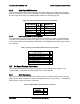
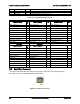
On the server board, this header is labeled “FRONT PANEL”. The following table provides the
pin-out for this header.
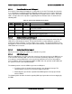
Table 26. SSI Front Panel Header Pin-out (Front Panel)
Signal Description
Pin#
Pin#
Signal Description
P3V3_AUX
1
2
P3V3_AUX
KEY
4
P5V_STBY
FP_PWR_LED_BUF_R_N
5
6
FP_ID_LED_BUF_R_N
P3V3
7
8
FP_LED_STATUS_GREEN_R_N
LED_HDD_ACTIVITY_R_N
9
10
FP_LED_STATUS_AMBER_R_N
FP_PWR_BTN_N
11
12
LED _NIC_LINK0_ACT_FP_N
GROUND
13
14
LED _NIC_LINK0_LNKUP_FP_N
FP_RST_BTN_R_N
15
16
SMB_SENSOR_3V3STBY_DATA_R0
GROUND
17
18
SMB_SENSOR_3V3STBY_CLK
FP_ID_BTN_R_N
19
20
FP_CHASSIS_INTRUSION
PU_FM_SIO_TEMP_SENSOR
21
22
LED_NIC_LINK1_ACT_FP_N
FP_NMI_BTN_R_N
23
24
LED_NIC_LINK1_LNKUP_FP_N
KEY
KEY
LED_NIC_LINK2_ACT_FP_N
27
28
LED_NIC_LINK3_ACT_FP_N
LED_NIC_LINK2_LNKUP_FP_
N
29
30
LED_NIC_LINK3_LNKUP_FP_N