
Technical Product Specification


Intel
®
Server System R1000EP Product Family TPS System Storage and Peripheral Options
Revision 2.0 Intel Order Number G67599-003 31
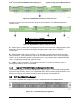
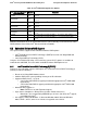
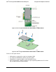
Figure 26. Hard Disk Drive Interface Front Connectors
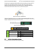
Several connectors are there on the backside of each backplane. The following illustration
identifies each:
Label
Description
A
Power connector
B
4-port Mini-SAS cable connectors
C
SMBus*-In cable connector – From Server board
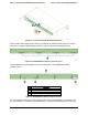
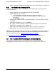
Figure 27. Hard Disk Drive Interface Rear Connectors
A – Power Harness Connector: The backplane includes a 2x2 connector supplying power to the
backplane. Power is routed to the backplane through a power cable harness from the
server board.
B – Multi-port Mini-SAS Cable Connectors: The backplane includes two multi-port mini-SAS
cable connectors, each providing I/O signals for four SAS/SATA hard drives on the backplane.
Cables can be routed from matching connectors on the server board, add-in SAS/SATA RAID
cards, or optionally installed SAS expander cards.
C – SMBus* Cable Connectors: The backplane includes a 1x5 cable connector used as a
management interface to the server board.
5.1.2 Cypress* CY8C22545 Enclosure Management Controller
The backplane supports enclosure management using a Cypress* CY8C22545 Programmable
System-on-Chip (PSoC*) device. The CY8C22545 drives the hard drive activity/fault LED, hard
drive present signal, and controls hard drive power-up during system power-on.
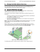
5.2 3.5" Hard Disk Drive Support
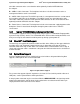
The server is available with support for four 3.5” hard disk drives as illustrated below.
Figure 28. 3.5" Hard Drive Bay Configuration