
Technical Product Specification

Intel
®
Server System R1000EP Product Family TPS Power Subsystem
Revision 2.0 Intel Order Number G67599-003 17
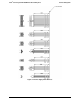
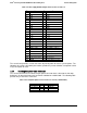
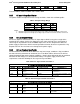
Table 3. Power Supply Module Output Power Connector Pin-out
Pin
Name
Pin
Name
A1
GND
B1
GND
A2
GND
B2
GND
A3
GND
B3
GND
A4
GND
B4
GND
A5
GND
B5
GND
A6
GND
B6
GND
A7
GND
B7
GND
A8
GND
B8
GND
A9
GND
B9
GND
A10
+12V
B10
+12V
A11
+12V
B11
+12V
A12
+12V
B12
+12V
A13
+12V
B13
+12V
A14
+12V
B14
+12V
A15
+12V
B15
+12V
A16
+12V
B16
+12V
A17
+12V
B17
+12V
A18
+12V
B18
+12V
A19
PMBus* SDA
B19
A0 (SMBus* address)
A20
PMBus* SCL
B20
A1 (SMBus* address)
A21
PSON
B21
12V stby
A22
SMBAlert#
B22
Cold Redundancy Bus
A23
Return Sense
B23
12V load share bus
A24
+12V remote Sense
B24
No Connect
A25
PWOK
B25
Compatibility Check pin*
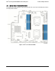
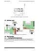
The server board provides several connectors to provide power to various system options. The
following sub-sections will identify the location, provide the pin-out definition, and provide a brief
usage description for each.
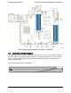
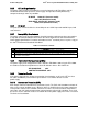
3.3.2 Hot Swap Backplane Power Connector
The server board includes one white 2x4-pin power connector that is cabled to the hot swap
backplane. On the server board, this connector is labeled as “HSBP PWR”. The following table
provides the pin-out for this connector:
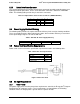
Table 4. Hot Swap Backplane Power Connector Pin-out (“HSBP PWR")
Signal Description
Pin#
Pin#
Signal Description
P12V_240VA
5
1
GROUND
P12V_240VA
6
2
GROUND
P12V_240VA
7
3
GROUND
P12V_240VA
8
4
GROUND