
Technical Product Specification


Intel
®
Server Board S2400EP TPS Power Supply Specification Guidelines
Revision 2.0 Intel order number G50763-002
115
The +12 V1, +12 V2, +12 V3, +12 V4, –12 V, and 5V SB outputs only use remote sense
referenced to the ReturnS signal. The remote sense input impedance to the power supply must
be greater than 200 on 3.3 VS and 5 VS. This is the value of the resistor connecting the
remote sense to the output voltage internal to the power supply.
Remote sense must be able to regulate out a minimum of 200 mV drop. The remote sense
return (ReturnS) must be able to regulate out a minimum of 200mV drop in the power ground
return. The current in any remote sense line should be less than 5 mA to prevent voltage
sensing errors.
The power supply must operate within specification over the full range of voltage drops from the
power supply’s output connector to the remote sense points.
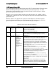
12.2.4 Voltage Regulation
The power supply output voltages stay within the following voltage limits when operating at
steady state and dynamic loading conditions. These limits include the peak-peak ripple/noise.
These shall be measured at the output connectors.
Table 57. Voltage Regulation Limits
Parameter
Tolerance
Min
Nom
Max
Units
+3.3V
- 3%/+5%
+3.20
+3.30
+3.46
Vrms
+5V
- 4%/+5%
+4.80
+5.00
+5.25
Vrms
+12V1
- 4%/+5%
+11.52
+12.00
+12.60
Vrms
+12V2
- 4%/+5%
+11.52
+12.00
+12.60
Vrms
+12V3
- 4%/+5%
+11.52
+12.00
+12.60
Vrms
- 12V
- 10%/+10%
- 13.20
-12.00
-10.80
Vrms
+5VSB
- 4%/+5%
+4.80
+5.00
+5.25
Vrms
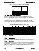
12.2.5 Dynamic Loading
The output voltages remain within limits specified for the step loading and capacitive loading
specified in the table below. The load transient repetition rate is tested between 50Hz and 5kHz
at duty cycles ranging from 10%-90%. The load transient repetition rate is only a test
specification. The step load may occur anywhere within the MIN load to the MAX
load conditions.
Table 58. Transient Load Requirements
Output
Step Load Size
(See note 2)
Load Slew Rate
Test capacitive Load
+3.3V
6.0A
0.5 A/sec
970 F
+5V
4.0A
0.5 A/sec
400 F
12V1+12V
2 +12V3
23.0A
0.5 A/sec
2200 F
1,2
+5VSB
0.5A
0.5 A/sec
20 F
Notes:
1. Step loads on each 12V output may happen simultaneously.
2. The +12V should be tested with 2200F evenly split between the four +12V rails.