
Technical Product Specification


Intel
®
Server Board S2400EP TPS On-board Connector/Header Overview
Revision 2.0 Intel order number G50763-002
93
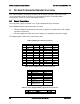
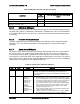
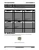
8.2.2 Front Panel USB Connector
The server board includes a 10-pin connector, that when cabled, can provide up to two USB
ports to a front panel. On the server board the connector is labeled “FP USB” and is located on
the front edge of the board. The following table provides the connector pin-out.
Table 30. Front Panel USB Connector Pin-out (FP USB)
Signal Description
Pin
#
Pin
#
Signal Description
P5V_USB_FP
1
2
P5V_USB_FP
USB2_P11_F_D
N
3
4
USB2_P13_F_D
N
USB2_P11_F_DP
5
6
USB2_P13_F_DP
GROUND
7
8
GROUND
10
TP_USB2_FP_10
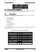
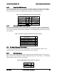
8.2.3 Intel
®
Local Control Panel Connector
The server board includes a 7-pin connector that is used when the system is configured with
the Intel
®
Local Control Panel with LCD support. On the server board this connector is labeled
“LCP” and is located on the front edge of the board. The following table provides the pin-out for
this connector.
Table 31. Intel
®
Local Control Panel Connector Pin-out (LCP)
Signal Description
Pin
#
SMB_SENSOR_3V3STBY_DATA_R0
1
GROUND
2
SMB_SENSOR_3V3STBY_CLK
3
P3V3_AUX
4
FM_LCP_ENTER_N_R
5
FM_LCP_LEFT_N_R
6
FM_LCP_RIGHT_N_R
7
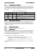
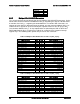
8.3 On-Board Storage Connectors
The server board provides connectors for support of several storage device options. This
section provides a functional overview and pin-out of each connector.
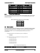
8.3.1 SATA Connectors
The server board includes two white ports SATA connectors capable of transfer rates of up to
6Gb/s. On the server board this connector is labeled as “SATA_0” and “SATA_1”. The following
table provides the pin-out for these connectors.
Table 32. AHCI SATA Controller Connector Pin-out
Signal
Description
Pin
#
GROUND
1
SATA_TXP
2