
Technical Product Specification


On-board Connector/Header Overview Intel
®
Server Board S2400EP TPS
Intel order number G50763-002 Revision 2.0
88
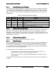
8. On-board Connector/Header Overview
This section identifies the location and pin-out for on-board connectors and headers of the
server board that provide an interface to system options/features, on-board platform
management, or other user accessible options/features.
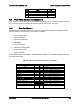
8.1 Power Connectors
The main power supply connection uses an SSI-compliant 2x12 pin connector.
Three additional power-related connectors also exist:
Two SSI-compliant 2x4 pin power connectors to provide 12-V power to the CPU voltage
regulators and memory.
One SSI-compliant 1x5 pin connector to provide I
2
C monitoring of the power supply.
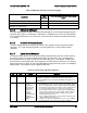
The following tables define these connector pin-outs:
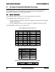
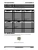
Table 23. Main Power Connector Pin-out
Pin
Signal
Color
Pin
Signal
Color
1
+3.3 Vdc
Orange
13
+3.3 Vdc
Orange
2
+3.3 Vdc
Orange
14
-12 Vdc
Blue
3
GND
Black
15
GND
Black
4
+5 Vdc
Red
16
PS_ON#
Green
5
GND
Black
17
GND
Black
6
+5 Vdc
Red
18
GND
Black
7
GND
Black
19
GND
Black
8
PWR_OK
Gray
20
NC
White
9
5 VSB
Purple
21
+5 Vdc
Red
10
+12 Vdc
Yellow
22
+5 Vdc
Red
11
+12 Vdc
Yellow
23
+5 Vdc
Red
12
+3.3 Vdc
Orange
24
GND
Black
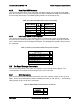
Table 24. CPU 1/CPU 2 Power Connector Pin-out
Pin
Signal
Color
1
GND of Pin 5
Black
2
GND of Pin 6
Black
3
GND of Pin 7
Black
4
GND of Pin 8
Black
5
+12 Vdc CPU1/2
Yellow/black
6
+12 Vdc CPU1/2
Yellow/black
7
+12 Vdc
DDR3_CPU1/2
Yellow/black
8
+12 Vdc
DDR3_CPU1/2
Yellow/black
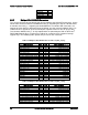
Table 25. Power Supply Auxiliary Signal Connector Pin-out
Pin
Signal
Color
1
SMB_CLK_FP_PWR_R
Orange