
Technical Product Specification


Functional Architecture Intel® Server Board S1400SP TPS
28 Intel order number G64248-003 Revision 2.1
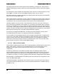
Supported I/O modules include:
Table 5. Supported Intel
®
I/O Module Options
Descritpion
Intel
®
Product Code
4-port 1Gb Ethernet Networking IO Module AXX4P1GBPWLIOM
2-port 10Gb Ethernet Networking IO Module AXX10GBTWLIOM
2-port 10Gb Ethernet SFP IO Module AXX10GBNIAIOM
FDR InfiniBand* IO Module AXX1FDRIOIOM
3.2.3.4 SAS Module
To broaden the standard on-board feature set, the server board provides support for one of
several available SAS RAID IO Module options. The SAS module is attached to a mezzanine
connector on the server board (J4J1) labeled SAS_Module and is supported by x4 PCIe Gen3
signals from the IIO module of the CPU processor.
3.2.3.5 Network Interface
Network connectivity is provided by means of one onboard Intel
®
Ethernet Controller I350
providing up to four 10/100/1000 Mb Ethernet ports. The NIC chip is supported by implementing
x2 PCIe Gen2 signals from the Intel
®
C600 PCH.
On the Intel
®
Server Board S1400SP, two for S1400SP2 and four for S1400SP4 external
10/100/1000 Mb RJ45 Ethernet ports are provided. Each Ethernet port drives two LEDs located
on each network interface connector. The LED at the right of the connector is the link/activity
LED and indicates network connection when on, and transmit/receive activity when blinking.
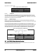
The LED at the left of the connector indicates link speed as defined in the following table:
Table 6. External RJ45 NIC Port LED Definition
LED Color LED State
NIC State
Green/Amber (Right) Off 10 Mbps
Amber 100 Mbps
Green 1000 Mbps
Green (Left) On Active Connection
Blinking Transmit/Receive activity
3.3 Intel
®
C600-A Chipset Functional Overview
The following sub-sections will provide an overview of the key features and functions of the
Intel
®
C600-A chipset used on the server board.