
Technical Product Specification


Intel® Server Board S1400SP TPS On-board Connector/Header Overview
Revision 2.1 Intel order number G64248-003
91
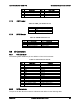
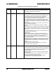
Table 45. Internal Type-A USB Connector Pin-out
Signal Description
Pin#
P5V_USB_INT 1
USB2_P2_F_DN 2
USB2_P2_F_DP 3
GROUND 4
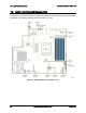
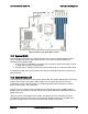
8.9 Other Connectors and Headers
The server board includes a 2-pin chassis intrusion header which can be used when the chassis
is configured with a chassis intrusion switch. On the server board, this header is labeled “CHAS
INTR” and is located on the front edge of the server board. The header has the following pin-
out.
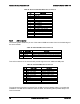
Table 46. Chassis Intrusion Header Pin-out ("CHAS_INTR")
Signal Description
Pin#
FP_CHASSIS_INTRUSION 1
GROUND 2
The server board includes a 2-pin hard drive activity LED header used with some SAS/SATA
controller add-in cards. On the server board, this header is labeled “HDD LED” and is located on
the left edge of the server board. The header has the following pin-out.
Table 47. Hard Drive Activity Header Pin-out ("HDD_LED")
Signal Description
Pin#
LED_HDD_ACT_N 1
TP_LED_HDD_ACT 2