
Technical Product Specification


Intel
®
Server System R1000SP Product Family TPS System Storage and Periferal Options
Revision 2.0 Intel Order Number G64249-002
41
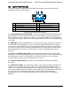
C – SMBus* Cable Connectors – The backplane includes a 1x5 cable connector used as a
management interface to the server board.
6.3.2
Cypress* CY8C22545 Enclosure Management Controller
The backplane supports enclosure management using a Cypress* CY8C22545 Programmable
System-on-Chip (PSoC*) device. The CY8C22545 drives the hard drive activity/fault LED, hard
drive present signal, and controls hard drive power-up during system power-on.
6.4
Optical Drive Support
Systems configured with four 3.5" hard drive bays also include a designated drive bay A to
support a SATA optical drive as illustrated below.
Figure 39. Optical Drive Support
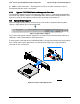
For systems that support eight 2.5" hard drives, the front I/O Panel, which provides video and
USB ports, can be replaced with a SATA optical drive.
A 2x3 pin power connector labeled “ODD/SSD PWR” is designed to provide power to the optical
drive. SATA signals for the optical drive are cabled from the white 7-pin single port SATA
connector on the server board.
Figure 40. Install a SATA Optical Drive