
Technical Product Specification


Platform Management Functional Overview Intel® Server Board S1400FP TPS
62 Intel order number G64246-003 Revision 2.0
levels are changed dynamically to cap throttling based on memory and system thermal
conditions as determined by the system and DIMM power and thermal parameters. The BMC’s
fan speed control functionality is linked to the memory throttling mechanism used.
The following terminology is used for the various memory throttling options:
Static Open Loop Thermal Throttling (Static-OLTT): OLTT control registers that are
configured by BIOS MRC remain fixed after post. The system does not change any of the
throttling control registers in the embedded memory controller during runtime.
Static Closed Loop Thermal Throttling (Static-CLTT): CLTT control registers are
configured by BIOS MRC during POST. The memory throttling is run as a closed-loop
system with the DIMM temperature sensors as the control input. Otherwise, the system
does not change any of the throttling control registers in the embedded memory controller
during runtime.
Dynamic Open Loop Thermal Throttling (Dynamic-OLTT): OLTT control registers are
configured by BIOS MRC during POST. Adjustments are made to the throttling during
runtime based on changes in system cooling (fan speed).
Dynamic Closed Loop Thermal Throttling (Dynamic-CLTT): CLTT control registers are
configured by BIOS MRC during POST. The memory throttling is run as a closed-loop
system with the DIMM temperature sensors as the control input. Adjustments are made to
the throttling during runtime based on changes in system cooling (fan speed).
Both Static and Dynamic CLTT modes implement a Hybrid Closed Loop Thermal Throttling
mechanism where the Integrated Memory Controller estimates the DRAM temperature in
between actual reads of the memory thermal sensors.
6.12
Messaging Interfaces
The BMC supports the following communications interfaces:
Host SMS interface by means of low pin count (LPC)/keyboard controller style (KCS)
interface.
Host SMM interface by means of low pin count (LPC)/keyboard controller style (KCS)
interface.
Intelligent Platform Management Bus (IPMB) I
2
C interface.
LAN interface using the IPMI-over-LAN protocols.
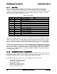
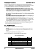
Every messaging interface is assigned an IPMI channel ID by IPMI 2.0.
Table 16. Messaging Interfaces
Channel ID
Interface
Supports
Sessions
0
Primary IPMB
No
1
LAN 1
Yes
2
LAN 2
Yes
3
LAN 3
1
(Provided by the Intel
®
Dedicated Server Management NIC)
Yes
4
Reserved
Yes
5
USB
No
6
Secondary IPMB
No
7
SMM
No