
Technical Product Specification


Intel® Server Board S1400FP TPS Platform Management Functional Overview
Revision 2.0 Intel order number G64246-003 61
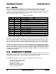
On-board Ethernet Controller Temperature Sensors
4, 6
Add-In Intel
®
SAS/IO Module Temperature Sensors
4, 6
PSU Thermal Sensor
4, 9
CPU VR Temperature Sensors
4, 7
DIMM VR Temperature Sensors
4, 7
Integrated BMC Temperature Sensor
4, 7
Global Aggregate Thermal Margin Sensors
3, 8
Note:
1. For fan speed control in Intel
®
chassis
2. For fan speed control in third party chassis
3. Temperature margin from throttling threshold
4. Absolute temperature
5. PECI value
6. On-die sensor
7. On-board sensor
8. Virtual sensor
9. Available only when PSU has PMBus*
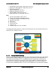
The following illustration provides a simple model showing the fan speed control structure that
implements the resulting fan speeds.
Figure 20. Fan Speed Control Process
6.11.9
Memory Thermal Throttling
The server board provides support for system thermal management through open loop throttling
(OLTT) and closed loop throttling (CLTT) of system memory. Normal system operation uses
closed-loop thermal throttling (CLTT) and DIMM temperature monitoring as major factors in
overall thermal and acoustics management. In the event that BIOS is unable to configure the
system for CLTT, it defaults to open-loop thermal throttling (OLTT). In the OLTT mode, it is
assumed that the DIMM temperature sensors are not available for fan speed control. Throttling