
Technical Product Specification


Platform Management Functional Overview Intel® Server Board S1400FP TPS
60 Intel order number G64246-003 Revision 2.0
6.11.7
Fan Profiles
The server system supports multiple fan control profiles to support acoustic targets and
American Society of Heating, Refrigerating, and Air Conditioning Engineers (ASHRAE)
compliance. The BIOS Setup utility can be used to choose between meeting the target acoustic
level or enhanced system performance. This is accomplished through fan profiles. The BMC
supports eight fan profiles, numbered from 0 to 7.
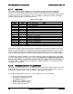
Table 15. Fan Profiles
Type
Profile
Details
OLTT
0
Acoustic, 300M altitude
OLTT
1
Performance, 300M altitude
OLTT
2
Acoustic, 900M altitude
OLTT
3
Performance, 900M altitude
OLTT
4
Acoustic, 1500M altitude
OLTT
5
Performance, 1500M altitude
OLTT
6
Acoustic, 3000M altitude
OLTT
7
Performance, 3000M altitude
CLTT
0
Acoustic, 300M altitude
CLTT
1
Performance, 300M altitude
CLTT
2
Acoustic, 900M altitude
CLTT
3
Performance, 900M altitude
CLTT
4
Acoustic, 1500M altitude
CLTT
5
Performance, 1500M altitude
CLTT
6
Acoustic, 3000M altitude
CLTT
7
Performance, 3000M altitude
Each group of profiles allows for varying fan control policies based on the altitude. For a given
altitude, the Tcontrol SDRs associated with an acoustics-optimized profile generate less noise
than the equivalent performance-optimized profile by driving lower fan speeds, and the BIOS
reduces thermal management requirements by configuring more aggressive memory throttling.
The BMC only supports enabling a fan profile through the command if that profile is supported
on all fan domains defined for the given system. It is important to configure platform Sensor
Data Records (SDRs) so that all desired fan profiles are supported on each fan domain. If
no single profile is supported across all domains, the BMC, by default, uses profile 0 and does
not allow it to be changed.
6.11.8
Thermal Sensor Input to Fan Speed Control
The BMC uses various IPMI sensors as input to the fan speed control. Some of the sensors are
IPMI models of actual physical sensors, whereas, some are “virtual” sensors whose values are
derived from physical sensors using calculations and/or tabular information.
The following IPMI thermal sensors are used as input to the fan speed control:
Front Panel Temperature Sensor
1
Baseboard Temperature Sensor
2
CPU Margin Sensors
3,5,6
DIMM Thermal Margin Sensors
3,5
Exit Air Temperature Sensor
1, 4, 8
PCH Temperature Sensor
4,6